AREC Settings
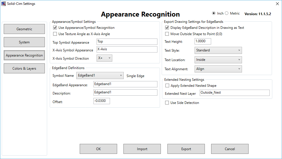
The AREC settings allow you to define what will occur when SCIM sees a particular appearance or symbol. The settings can be accessed through the Solid-CIM Settings (Command in AutoCAD: SCIMSET) and selecting the 'Appearance/Symbol Settings...' button.
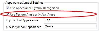
Use Appearance/Symbol Recognition: In order to use the appearances/symbols, you first need to select the checkbox after 'Use Appearance/Symbol Recognition'. If checked, SCIM will investigate the solid for any defined appearances or symbols during processing. If you are not using any of the AREC features, leave the box unchecked.
Once selected, you can define the way that SCIM interprets each situation.
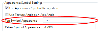
Top Symbol Appearance: The appearance name that is used to specify the top face of a part. When defining the name of the appearance within Autodesk Inventor, you can use the default 'TopSide' or specify your own unique name for the appearance. If you choose a name other then 'TopSide', you will need to change the value in this setting to match. By applying this appearance to a face of the solid will force that face to be the top of the part.
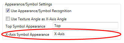
X-Axis Symbol Appearance: For defining the X-Axis (grain direction) in a part through Autodesk Inventor or any other 3D solid modeling software, you will need to apply the included X-Axis symbol. Appearances within Autodesk Inventor do not allow for an X-axis definition. This field should stay at the default setting.
Use Texture Angle as X-Axis Angle: In order to have Solid-CIM 3D evaluate an appearance that is set to a defined angle, this check box must be selected. To know more about how to use an appearance to define the X-Axis angle, please go to the 'Using an Appearance to Define X-Axis Angle Definition' section.
EdgeBand Definitions:
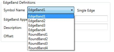
Symbol Name: The symbol name field allows you to select from the drop-down menu the available edgeband definitions.
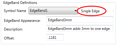
Once an edgeband definition is selected, the type of edgeband selected will appear on the right side of the drop-down menu.
You now have the ability to change the information that is associated with the selected edgeband.
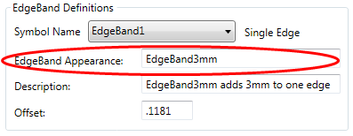
Edgeband Appearance: If you are using Autodesk Inventor, you can change the value of this field to match the appearance name that you will be using within Inventor to define the selected edgeband face.
If you are using a different solid modeling program, you would need to use the symbol for EdgeBand1 depending on the selection you made.
Description: This text will be displayed in the part drawing if the 'Display EdgeBand Description in Drawing as Text' option is checked. For more information on this feature, click here.
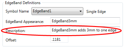
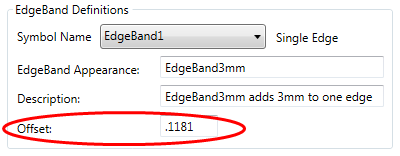
Offset: This value indicates the applied offset to the edge. a negative value will remove material from the part solid. A positive value will add material to the part solid. A zero value will have no affect on the part but will still state that an edgeband is being applied if you are using the 'Display EdgeBand Description in Drawing as Text' option.
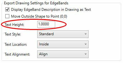
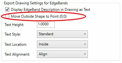
Export Drawing Settings for Edgebands:
The options contained within this field define how the edgeband is shown in the drawing file produced by SCIM.
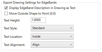
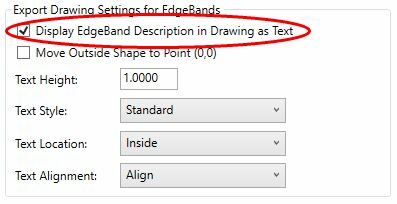
Display Edgeband Description in Drawing as Text: With this option checked, the edgeband type noted in the 'Symbol Name' drop-down menu will have the description associated with it inserted as a text field within the drawing (DWG) file.
Text Height: This will define the height of the text within the drawing (DWG) file for the edgeband description.
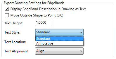
Text Style: A list of available defined text styles
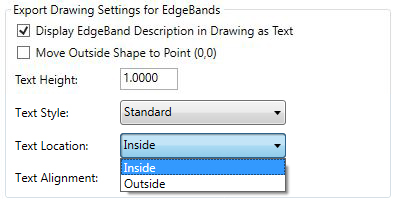
Text Location: Either Inside or Outside the SCIM defined part
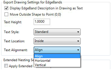
Text Alignment: Either Align with Edge, Horizontal or Vertical
Move Outside Shape to Point (0,0):
To use the Move Outside Shape to Point (0,0) feature, select the check box. This feature will adjust the Solid-CIM 3D result drawing to move the lower left point of the OUTSIDE layer geometry to 0,0 if an edgeband deduction was used.
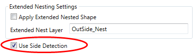
Extended Nesting Option:
To use the Extended Nesting Option feature, select the check box. For more information about 'Extended Nesting Option', click here.
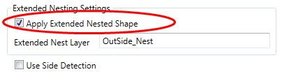
Use Side Detection:
To use the side detection feature, select the check box. For more information about 'Use Side Detection', click here.