![]()
Peck Bore is a Canned Cycle. That really means that it is a text based cycle that has several parameters which are fed to the machine controller so that all the holes choosen are cut in exactly the same manner, like a macro. In fact on most machines, Canned Cycles are an option and you should check your machine to see if it is equipped with this cycle before trying to use it. Typically, Canned Cycles are used to lessen the amount of NC Code necessary in a program when drilling a large amount of holes. There is a code savings because the Z moves up and down in each hole are not necessary. Another reason to use Canned Cycles is if you are writing code by hand, as there is less code to generate. Finally, if there is a chance that you are going to edit the code later by hand, a Canned Cycle leaves you with only one line to edit to change all the drilling parameters.
Canned Cycles use a series of commands on the first hole chosen and then perform those same commands on all other holes in the group. To use Canned Cycles, some explanation of them is necessary. This data is from the Fanuc control manual and will be specific to Fanuc controls or controls that can emulate the Fanuc code.
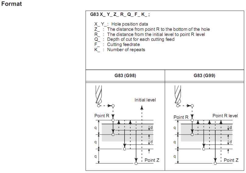
Basically this shows that depending on the Mode you use (G98 or G99) the tool will either retract to the Z level it started at or to the value specified by R in the cycle.
Here are two samples to demonstrate:
(DRILL .25 DIA.) |
(DRILL .25 DIA.) |
G28G91Z0M05 |
G28G91Z0M05 |
G90T2005M06 |
G90T2005M06 |
T102 |
T102 |
M03S10000 |
M03S10000 |
G00G17G55X1.Y1. |
G00G17G55X1.Y1. |
G00G43H5Z.375 |
G00G43H5Z.375 |
G98G83Z-.5R.125Q.1F100. |
G99G83Z-.5R.125Q.1F100. |
X2.Y2. |
X2.Y2. |
X3.Y3. |
X3.Y3. |
X4.Y4. |
X4.Y4. |
X5.Y5. |
X5.Y5. |
G80 |
G80 |
Truthfully, the two are hard to tell apart. Except for the mode command (G98/G99), the two samples are identical.
You will notice that after all the drilling parameters are called out, the next locations of the holes are just X, Y coordinates. The G83 starts the canned cycle and the G80 stops it, and every XY pair in between is a location.
The code shown above is explained in further detail below.
(DRILL .25 DIA.) |
G28G91Z0M05 |
G90T2005M06 |
T102 |
M03S10000 |
G00G17G55X1.Y1. <<-- Move to the first X, Y Hole location. |
G00G43H5Z.375 <<-- Set the initial height and move cutter to Z.375. |
G98G83Z-.5R.125Q.1F100. <<-- Set the drill parameters and drill the first hole to Z-.5 in increments of .1 at 100 IPM. |
X2.Y2. <<-- Drill the Second Hole. |
X3.Y3. <<-- Drill the Third Hole. |
X4.Y4. <<-- Drill the Fourth Hole. |
X5.Y5. <<-- Drill the Fifth Hole. |
G80 <<-- End the Canned Cycle. |
In Router-CIM, in order to use Canned Cycles, the holes MUST be grouped together. After Geoshaping the holes, use the Group command and group the shapes together forming one object in Router-CIM.
A short lesson in using Canned Cycles can be found here.