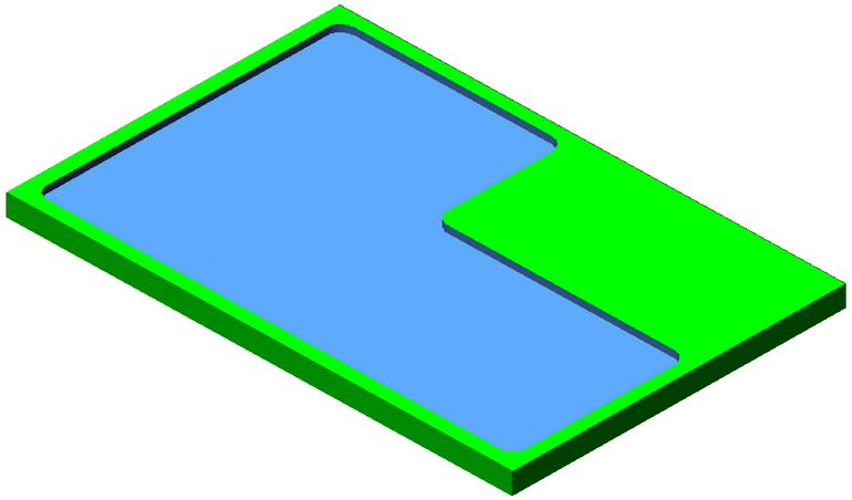
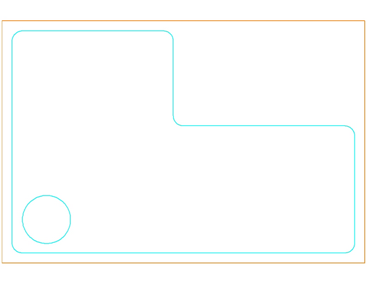
Linear Pocketing will move the tool across the shape to be cut in a straight back and forth pattern, removing material with each pass.
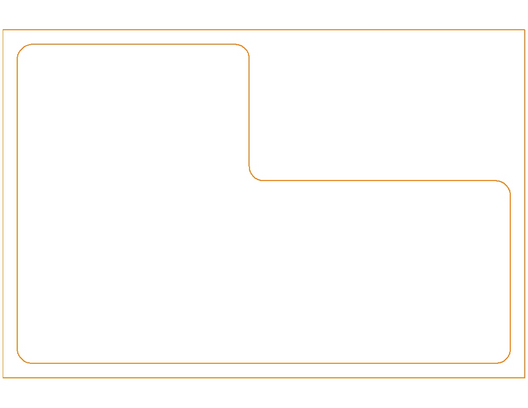
For the purpose of pocketing the above image, we want to remove the material in the inner shape, leaving the outer shape.
The inner shape is geoshaped. You may open this drawing and follow along. The drawing is available here.
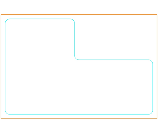
The start point is really irrelevant as we are using a linear algorithm to perform the pocketing so it will start at one ‘corner’ of the shape and work towards another.
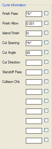
Starting with Linear Pocketing, the following settings are applied:
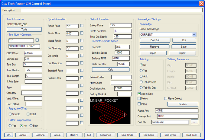
These setting are simply meant to display the Cycle Information parameters and how they are applied to a shape. The tool, feedrate, spindle speed and other tool related options will be determined by your material, tooling, shapes, etc.
The Cycle Parameters for the Linear Pocketing Cycle are:
Finish Pass - The amount that the tool will offset from the inside of the pocket and the outside of the islands. Using !*tr* will ensure that the tool radius will be used to avoid the edge.
Finish Allow - The value entered here will be added to the FINISH PASS field for a finishing allowance. If you are going to use another tool and/or another cycle to finish the edges of the part you may want to leave more material than just the tool radius for the finish pass. Placing a value here will add to the offset and leave material for a finishing tool to remove.
Island Finish - This allows you to specify the ISLAND FINISH. Valid responses here are Y or N. If N is specified, then Router-CIM will use the value stored in FINISH PASS. If Y is specified, then Router-CIM will highlight each island, and prompt you for a separate finish allowance for that island. This is in addition to the amount of the FINISH PASS.
Cut Spacing - This value is set to !*tr* by default, which will use the radius of the tool as the amount to step over between each pass. Depending on the size of the tool, thickness of the material and depth of cut you may want to specify another offset spacing. Realizing that any number smaller than the radius will be an overlap.
Cut Angle - This is a LINEAR POCKETING value only. Valid responses for this prompt are Y, N or a number. The default is N. If you specify Y, then Router-CIM will prompt you for an angle for the linear motion during the cut. If you enter a number, that will be the angle the pocket is cut at.
Cut Direction - This value applies only to SPIRAL POCKETING, for control of climb or conventional cutting. The two options for this parameter are CW or CCW. This is the control for climb cutting or convention cutting for the bulk of the cut with Spiral Pocketing
Standoff Pass – This option will allow you to specify either N (no) or a number for the offset amount of the tool around the edge of the shape. This will make a pass around the edge of the shape selected for pocketing offset by the input amount. If it is left blank or N is applied, then no such cutting pass will be made.
Collision Check - If you are pocketing out an area containing an island or islands, you may enter a Y in the collision check field and Router-CIM will search for tight areas in which your chosen tool might not fit based on the tool diameter and the spacing between the island and the edge of the pocket. In this case it will try and keep the tool from interfering with both the pocket and the island and still pocket as much of the shape as possible.
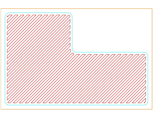
Using the values set previously, we get the following result:
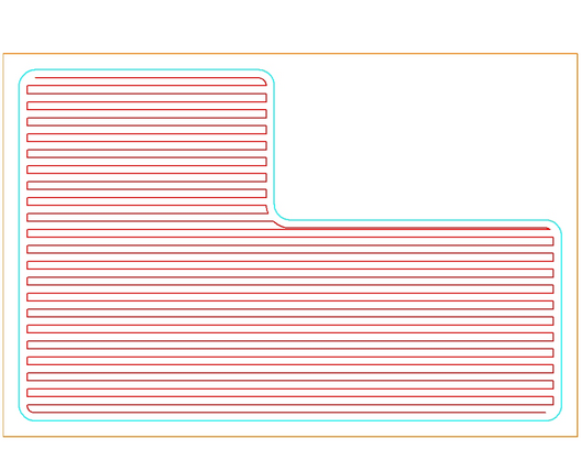
Note the very small overlap at the top of the extruded part of the shape. This is because the tool had to stay a tool radius away from the edge of the shape and step over for each individual pass by the radius of the tool (as set by Cut Spacing).
Cutting your part with these settings would produce the following result:
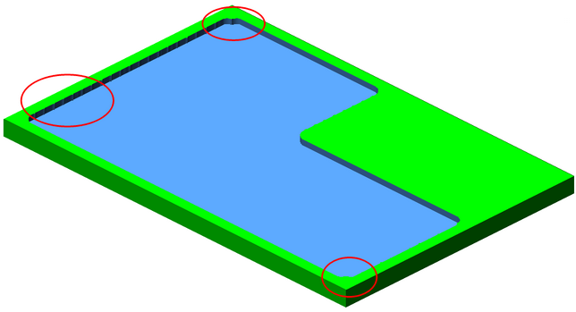
The pocket would be cut out, but there would be issues with the beginning and end of the shape and also small marks in the part where the tool stepped over to change directions.
Changing the Finish Pass from !*tr* to a number like 0.5 (the tool radius was 0.25, so this is twice as much), the result looks like this:
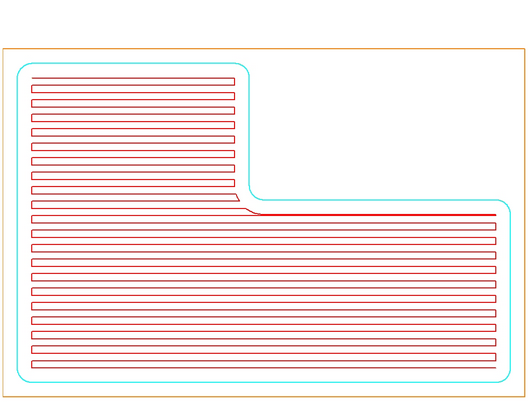
The toolpath is further from the edge of the shape and there would still be issues with the finish on the edge of the pocket. The net result of this is that there is more material left over for a finishing tool to remove.
Changing the Finish Pass or Island Finish would not have any direct effect on this shape, so the next variable is Cut Spacing. Changing this to 0.03 has this effect on the toolpath:
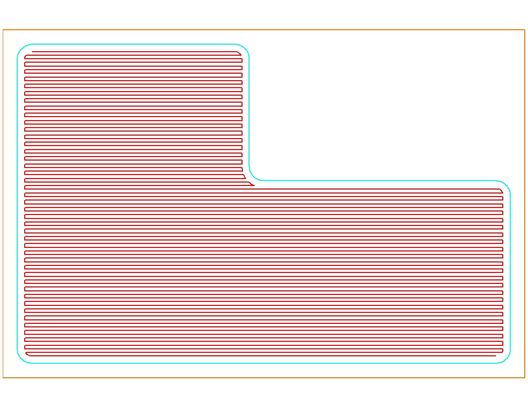
The space between the passed is much smaller and many more passes (and much more NC Code) will be required to pocket the shape.
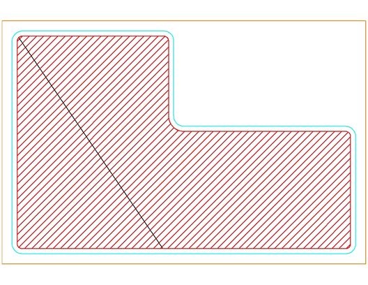
Changing the Cut Angle to 45 ( and putting the Cut Spacing back at !*tr* for clarity) will give the following result:
The toolpath is set at a 45° angle and the rest of the parameters will remain constant. The step over and finish amounts, etc.
Changing the Cut Direction will also not really have any effect on this shape since it is a linear pocket and each movement across the shape is moving in the opposite direction, alternating between a climb and conventional cut.
Changing the Standoff Pass to 0.25 (tool radius) results in the tool making a separate pass all the way around the shape like this:
Keep in mind that since pocketing is a roughing cycle, and not cutter compensation is involved, you may want to set the parameters to leave more material than the tool radius so that your finishing tool has some material to remove.
Using these settings, the pocket will be machined without any bad edges:
Placing a small island in the part will allow the demonstration of some of the other cycle features.
Placing this small circle and geoshaping it will allow us to make cuts that can consider the variables of Island Finish and Collision Check.
Setting the Island Finish to 0.25 and making a cut the following results show up. Keep in mind that this island was put intentionally close to the edge to demonstrate this result, by it also demonstrates that this result is possible and even likely if the geometry will allow it. Select CUT and the pick the larger shape first and then the smaller shape results in this:
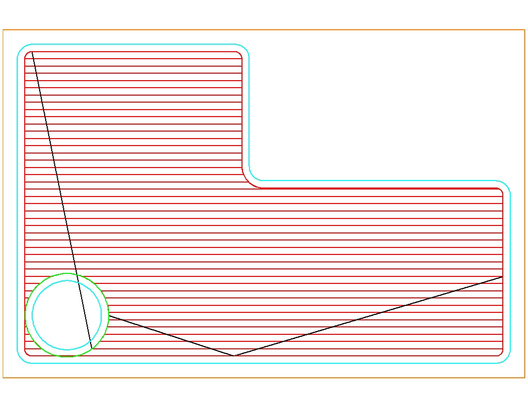
This is a clear violation of the part where the island is located, but the parameters tried to keep the Island Finish at 0.125 from the island and that resulted in an area that the pocketing was able to return this result. To fix this, we can use Collision Check. Setting this to Y results in:
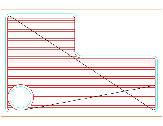
Note that the dark lines you see criss-crossing the part are index lines where the tool had to pick up and move to another location to start cutting again. This shape shows however that the Collision Check looked at the boundary of the shape and determined that a collision with the shape did occur and modified the toolpath geometry to suit. You should also note that in this shape, there is an area between the circle and the edge of the pocket that was not cut, because the tool did not fit. Machining the part with these settings would result in a part that looks like this:
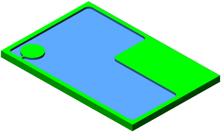
You must either use a smaller tool and make a finish pass around the island and the shape, or use a smaller tool for the entire pocket.