The next command prepares the geometry to receive a toolpath. The Geoshape command will make a copy of your geometry, place that copy on another layer and check your geometry for obvious circumstances (whether it is open or closed, for example), it then joins that copy together into a closed counter-clockwise polyline and places it on layer NC_SHAPE. This polyline contains information that Router-CIM can use to help the software generate the correct toolpath based on your settings in the control panel.
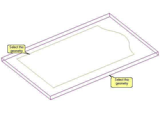
The shapes that need to be defined here are the inside and outside shapes of the door.
To get started, select the Geoshape button at the bottom of the Control Panel.
![]() Router-CIM Toolbar:
Router-CIM Toolbar: ![]()
![]() Command Line: AS
Command Line: AS
When you do you will see the following prompt in the command line of Router-CIM:
Select objects:
Pick on the outside and also the inside shapes of the door:
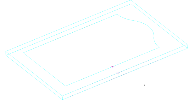
Once both of these shapes are selected, press Enter to accept the two choices. The geometry will turn colors to Cyan and display two purple X's on it showing the start points of each shape.
The following prompts appear:
2 object(s) selected!
Define Objects...
Collecting Geometry...
2 object(s) found.
Objects defined in Definition Library
Define Objects...
Blending: (Y) Forces all Selected Object(s) into a Single Shape,
(N) Creates Shape(s) from Selected Object(s), Joining to any Object(s)
Continuous with them. BLEND(Y/<N>):
Developing Shape(s)...
Defining Shape(s)...
Select Shapes for Start Point Editing
Select the Shape(s) that you want to Change the Start Point(s);
SELECT Previous for previously selected Object(s), or ENTER for NO Selection.
Select objects:
At this point you could change the start points of each of those shapes. Since you are now being prompted to Select Objects, any shape you select will allow you the option to change its start point.
Select the same two shapes again, then press Enter and you will see the following prompts:
Select objects: 1 found, 2 total
Select objects:
2 object(s) selected!
Locate the Shape Start Point.
Choose a point location:
Choose the midpoint of the right side of the door for each prompt (Osnaps are allowed or simple pick close to that area) and the start points will snap to that location. The drawing will now look like this:
Once the start points are there, press Enter to finish the command and return to the normal command prompt.
The purple start points will disappear and you will be left with the geometry ready to be cut.
Overview:
The basic idea here is to select geometry you want to send to Router-CIM to be cut via Geoshape, then allow Router-CIM to display the default start points for you. You then change the start points of any of the geometry you wish to edit, by selecting that geometry and then selecting where you want the start points to be located. Once you finish this command, and the geometry is Geoshaped, it does not need to be Geoshaped again. You can re-enter the start point command if you later wish to move the start point again, but unless you edit the geometry, you will not have to Geoshape the part again. At this point the part is ready for tool paths to be created.