To apply the tool paths to the part, we will select the proper tool, set the tool parameters as necessary, then select the cut cycle we wish to use for a specific cut, and modify any of the cycles parameters as necessary, then finally set any status or part specific data (like a depth of cut) and then make a tool path.
This process will be repeated for each tool and shape necessary to cut the part as desired.
![]() Control Panel Toolbar:
Control Panel Toolbar: ![]()
![]() Command Line: AS
Command Line: AS
Once you are in the control panel, you will need to set up the first cut.
You want to start with selecting the tool, then the cycle, and finally setting up the status information like feedrate, depth of cut, etc.
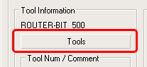
Select the Tool button on the Control Panel:
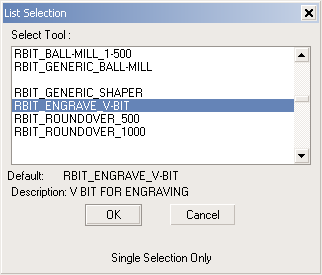
Scroll down the list of available tools until you see RBIT_ENGRAVE_V-BIT.
Select that tool and the select the OK button.
Once the tool is selected, you will change the tool number to another position.
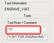
Change the number from "1" to "3". This might represent a different pocket in a tool changer or perhaps another spindle.
The next item you will change is the cycle that is going to be used to cut that shape. The current cycle is an outside cut cycle and you want to cut the inside shape as a center line cut with no offset.
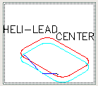
To change the cycle, pick on the small picture of the cycle on the Control Panel. This will open up a new selection of choices on cut cycles. All the cycles are explained later in this manual. For now select the Heli-Lead Center cycle.
If you select this and then select the OK button ( or double-click the picture) you will return to the Control Panel.
Once you are back at the Control Panel, the Heli-Lead Center cycle should show up in the lower left corner as a picture replacing the outside cut that was there earlier.
The last piece of data you need to create the toolpath is the status information. For this example, we are going to change the depth of the cut, the feedrate of the cut and the spindle speed.
You can set those items in the third column labeled Status Information on the Control Panel.
Set them up as shown here:
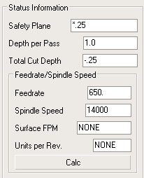
The depth is set to -.25 (cutting 1/4" deep into the material) and the feedrate and spindle speed are set to reflect the values needed for that cut.
After these values are set, you can select the CUT button ![]() on the Control Panel.
on the Control Panel.
Select the Inside Shape when prompted, and then press Enter. The command line will show the following prompts:
SELECT Shape(s) to Cut.
Select objects: 1 found
Select objects:
1 object(s) selected!
Router-CIM Cutting Cycles...
Establishing Cutting Plane...
Determining Tooling requirements...
Creating Tool Path...
NC Text : SPEED/14000.00000
NC Text : INDEXGROUP/4
NC Text : FEDRAT/325.00000000
NC Text : CIRCINT/0
Recording Results...
Knowledge Stored with Cycle.
Router-CIM Cycle development Completed.
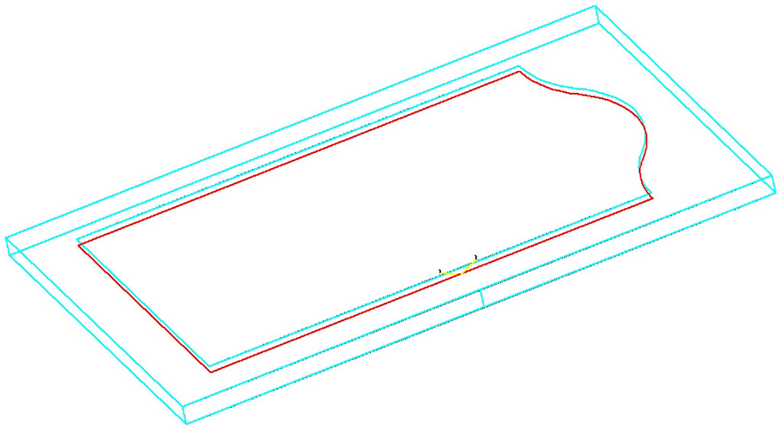
Then you should see a toolpath around the inside geometry that looks like the one shown here. You will then be returned to the Control Panel to set up the next cut.
For the next cut, you will be using the same techniques, but using a different tool, a new cycle, and different status information.
Change your Control Panel to make the following conditions:
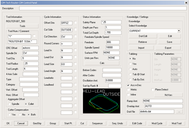
This is a 1/2" router bit, set as tool #1, and the cycle is Heli-Lead Outside. The depth is set to -.755 and the feedrate is 800. The spindle speed has been changed to 18000 RPM.
Once those conditions are set, use the Cut button again and select the Outside geometry when prompted. The command line will look like this:
SELECT Shape(s) to Cut.
Select objects: 1 found
Select objects:
1 object(s) selected!
Router-CIM Cutting Cycles...
Establishing Cutting Plane...
Determining Tooling requirements...
Creating Tool Path...
NC Text : SPEED/18000.00000
NC Text : INDEXGROUP/4
NC Text : CUTCOM/LEFT
NC Text : FEDRAT/400.00000000
NC Text : CUTCOM/OFF
NC Text : CIRCINT/0
Recording Results...
Knowledge Stored with Cycle.
Router-CIM Cycle development Completed.
And you should see a toolpath around the outside of the shape like this:
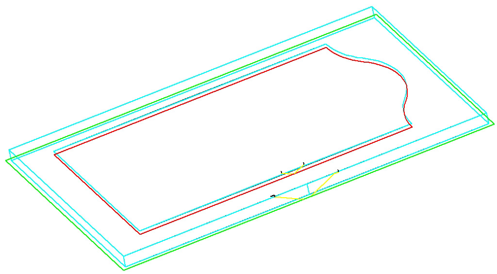
Those tool paths are all that are needed on this part. The next phase will be turning those tool paths into useable nc code.
The process of creating the tool paths is to select a tool, and change it's parameters if necessary to set the proper comment or tool number, or even size. Next you select the cut cycle that you want to use for the shape you want to cut. Last, set any status type data such as the depth of the cut or the speed and feedrate of the cut. Once you have set all the parameters necessary, you can make a tool path.