The Sequence is the final step in Router-CIM and the result of the Sequence command is machine-ready NC Code. The Sequencer in Router-CIM is user programmable, though most of the options, if not all, should be pre-set for your machine by Komo. A comprehensive look at the Sequencer is found in a later chapter of this manual.
To get nc code from the tool paths you have created, you can select the Sequence button on the Control Panel. You will then be prompted to Select Objects. For this sample, select the Inside cut first, then the Outside cut second. Once both cuts are selected, press Enter and you will see the NC Sequence Builder window.
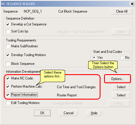
You can select the options for Perform Machine Calc and Report Information as shown to get a tool list in the code. Once you have checked those two boxes (Make NC Code should already be checked), select the Options button on the right. This will open the Sequence Options window.

In the Sequence Options, you can set the program number for the program you are about to make as well as setting some other program related options. For this example, place the number 1234 in the Job Identification Number box to set the program number to 1234. This could be any number up to four digits long.
Next set the Material Thickness to 0.75. This is how you set the code up to reflect the top of the spoil board as Z0. Last, set the Generate MCU comments to No. Then click on the OK button.
You will see the NC Sequence Builder window again, and you can select OK to that window as well.
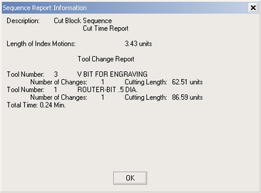
The Sequence Report will display showing the tools being used and their cutting length and time. Select OK.
The next thing you should see is an NC Code file appear on the screen over the top of your Autocad drawing.
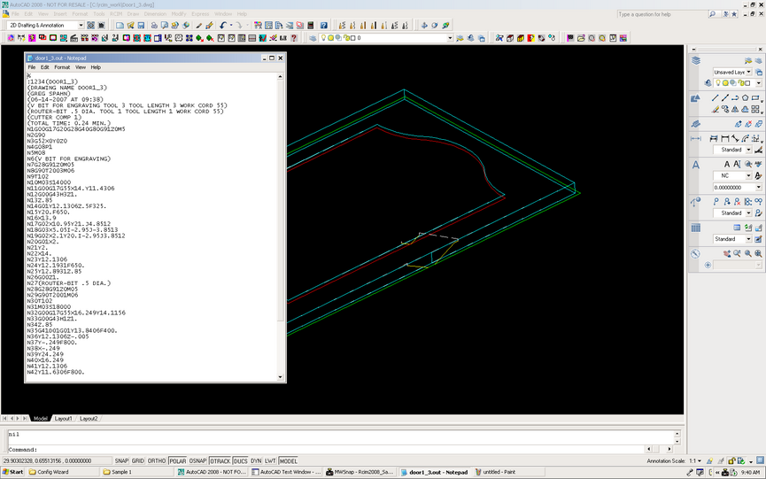
The code file generated is what is needed by the machine tool to make the part as drawn. The steps for creating the code are the same for any part, varying by the number of cuts and type of tools. You can always follow the steps outlined to make tool paths and nc code for a part.
| • | Geoshape your part, and select your start points. |
| • | Select a Tool, Cycle, and set Status data for a cut. |
| • | Make the cut. |
| • | Repeat the Tool, Cycle and Status settings for each piece of geometry you need to cut until all your tool paths have been created. |
| • | Make a Sequence from the tool paths. |
This concludes the first Sample. You can continue with more advanced topics in Sample #2, and a small lesson on Automation in Sample #3.