|
|

|

|
|||
|
|
|
|
Top Side Features: OutSide_ CutOut_ CutOut_X.XXXX_RND_ PktCutOut_ PktCutOut_X.XXXX_BALL_ Hole_ DadoRec_ DadoLine_ RabbetRec_ RabbetLine_ Slot_End_ Slot_Ball_ Bevel_ BevelInside_ Pocket_ PocketInside_ PocketOutside_ Profile_X.XXXX_RND_ Profile_X.XXXX_BALL_ ToeKick CBore_ CSink_ DoveTailDadoRec_ DoveTailDadoLine_ Embossed_ PBore_
|
Front Side (Horizontal) Features: PktCutOutFRONT_ HoleFRONT_ DadoRecFRONT_ DadoLineFRONT_ RabbetRecFRONT_ RabbetLineFRONT_ Slot_EndFRONT_ Slot_BallFRONT_ ProfileFRONT_ CBoreFRONT_ CSinkFRONT_ EmbossedFRONT_
Back Side (Horizontal) Features: PktCutOutBACK_ HoleBACK_ DadoRecBACK_ DadoLineBACK_ RabbetRecBACK_ RabbetLineBACK_ Slot_EndBACK_ Slot_BallBACK_ ProfileBACK_ CBoreBACK_ CSinkBACK_ EmbossedBACK_
|
Right Side (Horizontal) Features: PktCutOutRIGHT_ HoleRIGHT_ DadoRecRIGHT_ DadoLineRIGHT_ RabbetRecRIGHT_ RabbetLineRIGHT_ Slot_EndRIGHT_ Slot_BallRIGHT_ ProfileRIGHT_ CBoreRIGHT_ CSinkRIGHT_ EmbossedRIGHT_
Left Side (Horizontal) Features: PktCutOutLEFT_ HoleLEFT_ DadoRecLEFT_ DadoLineLEFT_ RabbetRecLEFT_ RabbetLineLEFT_ Slot_EndLEFT_ Slot_BallLEFT_ ProfileLEFT_ CBoreLEFT_ CSinkLEFT_ EmbossedLEFT_ |
Bottom Side Features: PktCutOutBOTTOM__ PktCutOutBOTTOM_X.XXXX_BALL_ HoleBOTTOM_ DadoRecBOTTOM_ DadoLineBOTTOM_ RabbetRecBOTTOM_ RabbetLineBOTTOM_ Slot_EndBOTTOM_ Slot_BallBOTTOM_ BevelBOTTOM_ BevelInsideBOTTOM_
|
PocketBOTTOM_ PocketInsideBOTTOM_ PocketOutsideBOTTOM_ ProfileBOTTOM_X.XXXX_RND_ ProfileBOTTOM_X.XXXX_BALL_ CBoreBOTTOM_ CSinkBOTTOM_ DoveTailDadoRecBOTTOM_ DoveTailDadoLineBOTTOM_ EmbossedBOTTOM_ |
|
Inch Mode: 4 Decimal Points
Metric Mode: 2 Decimal Points
Note: Angle definitions will always be 2 decimal points regardless of Inch Mode or Metric Mode.
Layer Name: |
Convention: |
Description: |
OutSide_0.7500 OutSide_19.05 |
Designated layer name followed by the DEPTH of the solid that Solid-CIM 3D found. This layer will always be followed by a single number. |
Every part will have an outside boundary. The geometry that Solid-CIM 3D places on the layer OUTSIDE will represent the boundary of the part that nesting will use to nest the parts together. |
|
|
|
Non-Circular Feature: Cutout_0.7500 Cutout_19.05 Circular Feature: Cutout_10.0000_0.7500 Cutout_254.00_19.05 |
Designated layer name followed by the DEPTH of the feature that Solid-CIM 3D found. This layer will be followed by a single number if it is non-circular. If the feature is a circle, Solid-CIM 3D will follow the layer with 2 numbers. The first number will be the DIAMETER of the circle and the second number will be the DEPTH of the feature. |
A feature that Solid-CIM 3D finds within the interior of the solid that goes all the way through the solid will be placed on the layer CUTOUT.
*The thickness of the feature may not be the same as the thickness of the solid itself. Solid-CIM 3D may define the thickness as less then the solid if the CUTOUT feature is within another feature (Feature-In-Feature). |
|
|
|
Non-Circular Feature: PktCutout_0.2500 PktCutout_6.35 Circular Feature: PktCutout_10.0000_0.2500 PktCutout_254.00_6.35 |
Designated layer name followed by the DEPTH of the feature that Solid-CIM 3D found. This layer will be followed by a single number if it is non-circular. If the feature is a circle, Solid-CIM 3D will follow the layer with 2 numbers. The first number will be the DIAMETER of the circle and the second number will be the DEPTH of the feature. |
A feature that Solid-CIM 3D finds within the interior of the solid that does NOT go all the way through the solid will be placed on the layer PKTCUTOUT. |
|
|
|
Cutout and PktCutout when using 'Include Width and Radius in Cutout Layer' Feature For more information on this feature, click here. |
||
CutOut_R0.1250_W0.3750_19.05 CutOut_R3.18_W9.53_19.05
|
Designated layer name followed by the MINIMUM RADIUS (if applicable) and MINIMUM WIDTH (if applicable) then DEPTH of the feature that Solid-CIM 3D found.
R - Minimum Radius found in the feature W - Minimum Width found in the feature |
A feature that Solid-CIM 3D finds within the interior of the solid that goes all the way through the solid will be placed on the layer CUTOUT and is using 'Include Width and Radius in Cutout Layer' feature.
*The thickness of the feature may not be the same as the thickness of the solid itself. Solid-CIM 3D may define the thickness as less then the solid if the CUTOUT feature is within another feature (Feature-In-Feature). |
|
|
|
PktCutOut_R0.1250_W0.3750_0.2500 PktCutOut_R3.18_W9.53_6.35
|
Designated layer name followed by the MINIMUM RADIUS (if applicable) and MINIMUM WIDTH (if applicable) then DEPTH of the feature that Solid-CIM 3D found.
R - Minimum Radius found in the feature W - Minimum Width found in the feature |
A feature that Solid-CIM 3D finds within the interior of the solid that does NOT go all the way through the solid will be placed on the layer PKTCUTOUT and is using 'Include Width and Radius in Cutout Layer' feature. |
|
|
|
Through Circular Feature According to Solid-CIM Settings: Hole_0.1969_Thru Hole_5.00_Thru
|
Designated layer name followed by the DIAMETER and DEPTH of the feature that Solid-CIM 3D found. The first number will be the DIAMETER of the circle and the second number will be the DEPTH of the feature for non-through circles OR the phrase "THRU" for through circles according to the Solid-CIM 3D settings. |
A feature that Solid-CIM 3D finds that is circular and is equal to or less then the Solid-CIM 3D setting of 'Maximum Diameter to be considered a Hole'. |
Note: Refer to the 'Hole Settings' in the Geometric Settings section for more options when a feature is a through Hole. |
||
Non-Through Circular Feature According to Solid-CIM Settings: Hole_0.1969_0.2500 Hole_5.00_6.35 |
Designated layer name followed by the DIAMETER and DEPTH of the feature that Solid-CIM 3D found. The first number will be the DIAMETER of the circle and the second number will be the DEPTH of the feature for non-through circles OR the phrase "THRU" for through circles according to the Solid-CIM 3D settings.
Horizontal 'HOLE' features are picked up on the 0 (FRONT), 90 (RIGHT), 180 (BACK), 270 (LEFT) degrees only. |
|
|
|
|
DadoRec_0.7500_0.2500 DadoRec_19.05_6.35 |
Designated layer name followed by the WIDTH of the Dado feature and the DEPTH of the Dado feature. The recognition of this feature is related to the Solid-CIM 3D setting of 'Produce a Dado as a Rectangle' being checked. |
A feature that Solid-CIM 3D finds that is a rectangular feature within the interior of the solid. The feature can intersect perpendicularly with the edge of the solid in 1 or 2 sides or be completely within the interior of the part. The recognition of this feature is related to the Solid-CIM 3D setting of 'Maximum Width to be considered a Dado' and checking the option of 'Produce a Dado as a Rectangle'. Solid-CIM 3D will draw the geometry as a rectangular feature. Solid-CIM 3D will extend an edge(s) if they intersect with the solid edge by a distance defined by 'Extension Distance of a Dado past edge of part' in the Solid-CIM 3D settings. |
|
|
|
DadoLine_0.7500_0.2500 DadoLine_19.05_6.35 |
Designated layer name followed by the WIDTH of the Dado feature and the DEPTH of the Dado feature. The recognition of this feature is related to the Solid-CIM 3D setting of 'Produce a Dado as a Rectangle' being unchecked. |
A feature that Solid-CIM 3D finds that is a rectangular feature within the interior of the solid. The feature must intersect perpendicularly with the edge of the solid in 1 or 2 sides or be completely within the interior of the part. The recognition of this feature is related to the Solid-CIM 3D setting of 'Maximum Width to be considered a Dado' and unchecking the option of 'Produce a Dado as a Rectangle'. Solid-CIM 3D will draw the geometry as a line feature from midpoint to midpoint of the rectangular feature it found. Solid-CIM 3D will extend an endpoint(s) if they intersect with the solid edge by a distance defined by 'Extension Distance of a Dado past edge of part' in the Solid-CIM 3D settings. |
|
|
|
RabbetRec_0.7500_0.2500 RabbetRec_19.05_6.35 |
Designated layer name followed by the WIDTH of the Rabbet feature and the DEPTH of the Rabbet feature. The recognition of this feature is related to the Solid-CIM 3D setting of 'Produce a Rabbet as a Rectangle' being checked. |
A feature that Solid-CIM 3D finds that is a rectangular feature that intersects 3 edges of the solid. The feature must intersect perpendicularly with the edge of the solid. The recognition of this feature is related to the Solid-CIM 3D setting of 'Maximum Width to be considered a Rabbet' and checking the option of 'Produce a Rabbet as a Rectangle'. Solid-CIM 3D will draw the geometry as a rectangular feature. Solid-CIM 3D will extend the 3 edges that intersect the solid by a distance defined by 'Extension Distance of a Rabbet past edge of part' in the Solid-CIM 3D settings. |
|
|
|
RabbetLine_0.7500_0.2500 RabbetLine_19.05_6.35 |
Designated layer name followed by the WIDTH of the Rabbet feature and the DEPTH of the Rabbet feature. The recognition of this feature is related to the Solid-CIM 3D setting of 'Produce a Rabbet as a Rectangle' being unchecked. |
A feature that Solid-CIM 3D finds that is a rectangular feature that intersects 3 edges of the solid. The feature must intersect perpendicularly with the edge of the solid. The recognition of this feature is related to the Solid-CIM 3D setting of 'Maximum Width to be considered a Rabbet' and unchecking the option of 'Produce a Rabbet as a Rectangle'. Solid-CIM 3D will draw the geometry as a line feature from midpoint to midpoint of the rectangular feature it found. Solid-CIM 3D will extend the line feature by a distance defined by 'Extension Distance of a Rabbet past edge of part' in the Solid-CIM 3D settings. |
|
|
|
Slot_End_0.5000_0.2500 Slot_End_12.70_6.35 |
Designated layer name followed by the WIDTH of the Slot feature and the DEPTH of the Slot feature if the Slot feature has a flat bottom. |
A feature that Solid-CIM 3D finds as a rectangular feature that has arcs at one or both ends with the diameter of the arc equal to the width of the rectangle and the arc intersects the rectangle at the quadrants. The _End designation is if the Slot feature has a flat bottom. |
|
|
|
Slot_Ball_0.5000_0.5000 Slot_Ball_12.70_12.70 |
Designated layer name followed by the WIDTH of the Slot feature and the DEPTH of the Slot feature if the Slot feature has an arced bottom. |
A feature that Solid-CIM 3D finds as a rectangular feature that has arcs at one or both ends with the diameter of the arc equal to the width of the rectangle and the arc intersects the rectangle at the quadrants. The _Ball designation is if the Slot feature has an arced bottom with the diameter of the arced bottom equal to the width of the rectangle. |
|
|
|
Bevel_45.00_0.5000_0.5000 Bevel_45.00_12.70_12.70 |
Designated layer name followed by the ANGLE of the Bevel feature, distance from the top of the solid to the edge of the solid and the DEPTH of the Bevel feature.
Solid-CIM 3D will only recognize a Bevel on a straight edge. |
A feature that Solid-CIM 3D finds as an angular feature such as a chamfer on the edge of a part. This type of feature will only be recognized on a straight edge and is on the outside of the 3D solid. |
|
|
|
BevelInside_45.00_0.5000_0.5000 BevelInside_45.00_12.70_12.70 |
Designated layer name followed by the ANGLE of the Bevel feature, distance from the top of the solid to the edge of the solid and the DEPTH of the Bevel feature when the Bevel feature is located on a Cutout.
Solid-CIM 3D will only recognize a Bevel on a straight edge. |
A feature that Solid-CIM 3D finds as an angular feature such as a chamfer on the edge of a part. This type of feature will only be recognized on a straight edge and is on the inside of the 3D solid. |
|
|
|
Pocket_0.2500 Pocket_6.35 |
Designated layer name followed by the DEPTH of the feature that Solid-CIM 3D found and it is found that there is an island feature within the feature. |
A feature that Solid-CIM 3D finds within the interior of the solid that does NOT go all the way through the solid will be placed on the layer Pocket if it also finds an island feature within the feature. This will trigger Router-CIM Automation Suite to look for the island feature when it is using a pocketing cycle. |
|
|
|
PocketInside_0.2500 PocketInside_6.35 |
Designated layer name followed by the DEPTH of the feature that Solid-CIM 3D found and it is found that there is an island feature within the feature.
The recognition of this feature is related to the Solid-CIM 3D setting of 'Create Additional Pocket Geometry' being checked. |
If Solid-CIM 3D recognizes a feature as a POCKET, Solid-CIM 3D will create and additional piece of geometry on the island features that it finds allowing for a finishing pass on with an outside profile cut on the islands. |
|
|
|
PocketOutside_0.2500 PocketOutside_6.35 |
Designated layer name followed by the DEPTH of the feature that Solid-CIM 3D found and it is found that there is an island feature within the feature.
The recognition of this feature is related to the Solid-CIM 3D setting of 'Create Additional Pocket Geometry' being checked. |
If Solid-CIM 3D recognizes a feature as a POCKET, Solid-CIM 3D will create and additional piece of geometry on the perimeter of the POCKET that it finds allowing for a finishing pass on with an inside profile cut on the perimeter of the POCKET geometry. |
|
|
|
Toekick |
Designated layer name only. The recognition of this feature is related to the Solid-CIM 3D setting of 'Include ToeKicks as part of Outside Shape' being unchecked. |
A feature that Solid-CIM 3D finds that is a rectangular feature that intersects 2 adjacent edges of a rectangular solid. The feature must intersect perpendicularly with the edge of the solid. The recognition of this feature is related to the Solid-CIM 3D setting of 'Include ToeKicks as part of Outside Shape' being unchecked. Solid-CIM 3D will draw the geometry as a line feature in a CCW rotation. The knowledge to cut this feature would need to use the cycle 'Left Hand Cut'. |
|
|
|
Cbore_0.7500_0.2500 Cbore_19.05_6.35 |
Designated layer name followed by the DIAMETER and DEPTH of the feature that Solid-CIM 3D found. |
A feature that Solid-CIM 3D finds that is circular AND has an inclusive circular feature that is located from the center point of the outer circular feature. The outer circular feature will be placed on the layer Cbore with the inner circle placed on layer Hole. |
|
|
|
Csink_0.7500_0.2500_90.00 Csink_19.05_6.35_90.00 |
Designated layer name followed by the DIAMETER, DEPTH and ANGLE of the feature that Solid-CIM 3D found. |
A feature that Solid-CIM 3D finds that is circular AND has an inclusive circular feature that is located from the center point of the outer circular feature with an ANGLE between the two circular features. The outer circular feature will be placed on the layer Csink with the inner circle placed on layer Hole. |
|
|
|
Embossed_0.0625 Embossed_1.59 |
Designated layer name followed the DEPTH of the feature Solid-CIM 3D found. |
A feature that Solid-CIM 3D finds that is less then 0.1 inch in depth AND has a volume less then 0.001 will be placed on a layer called Embossed. |
|
|
|
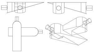
PBore_0.5000_0.5000 (See Pocket Bores section) |
Designated layer name followed by the WIDTH of the Pocket Bore feature and the DEPTH of the Pocket Bore feature. The horizontal hole feature will be on the appropriate 'HOLE' layer.
Note: The horizontal hole feature can only be recognized on the 0, 90, 180 and 270 degree angles. |
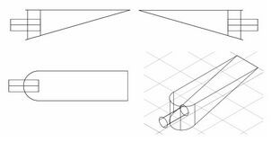
A Pocket Bore for Solid-CIM 3D is defined as the union of two features. The first feature is similar to a Slot definition from Solid-CIM 3D, where the diameter of the semi-circle is equal to the rectangle width. The second feature is a horizontal hole that intersects at the quadrant of the circle, where the center point of the circle is at half of the total depth. (See Pocket Bores section) |
|
|
|
|
|
|
Profile_0.2500_RND_0.2500 Profile_6.35_RND_6.35 |
Designated layer name for a rounded (fillet) edge on the outside of a feature. |
See Rounded Edges section. |
|
|
|
Cutout_0.2500_RND_0.2500 Cutout_6.35_RND_6.35 |
Designated layer name for a rounded (fillet) edge on the inside of a feature. |
See Rounded Edges section. |