Geometric Settings
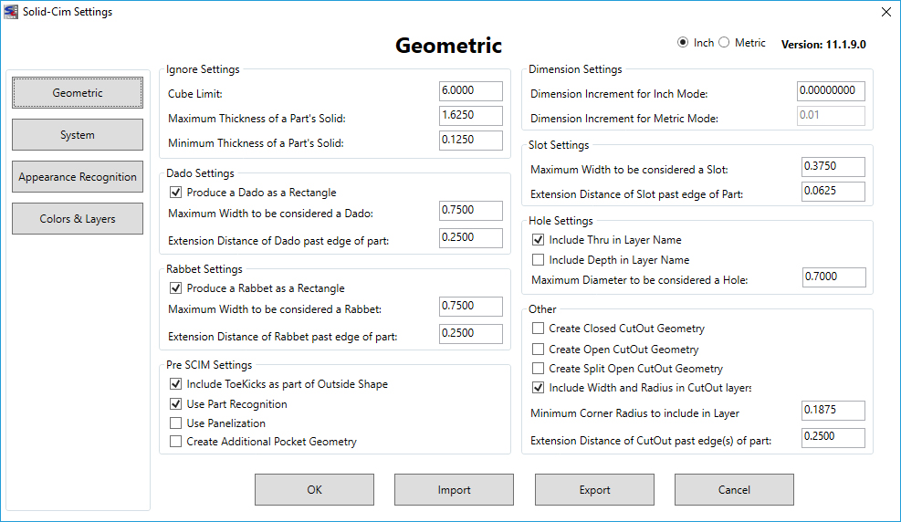
The settings below are represented in Inches.
Ignore Settings:
The settings in this section are used to define what Solid-CIM will include and ignore when processing
Cube Limit <6.00>: Any solid found that fits totally inside a box with the measurement of “Cube Limit” will be ignored by Solid-CIM 3D and placed on the ignored layer. This filters outs solids that are hardware objects and not parts to be cut.
Maximum thickness of a part's solid <1.6250>: All curved parts are ignored and any flat parts that have a thickness greater than this “Maximum” value. A solid is lay downed flat and the thickness is determined by the solid’s extents in Z.
Minimum thickness of a part's solid <0.1250>: Same as described in “Maximum” except this is for the “Minimum” thickness. Any thickness less than this value is ignored.
Dado Settings:
The settings in this section are used when a Dado feature is found when running Solid-CIM
Produce a Dado as a rectangle [DadoRec] (Y/N) <Yes>: Yes = the Dado will be a rectangle around the Dado feature on the DadoRec layer. No = the Dado will be a straight polyline true the center of the Dado feature on the DadoLine layer.
Maximum Dado Width to be considered a Dado <0.7500>: Any Dado feature that has a width greater than this value will be a CutOut. If you need all Dado type features to always be CutOut than set this value to zero.
Extension distance of Dado past edge of part <0.2500>: This value will extend the length of the Dado past the edge of the part at the distance entered for this setting. This setting will be applied to the DadoRec and DadoLine polylines described in setting #5. This setting is not applied to the CutOut polyline described in setting #6.
Rabbet Settings:
The settings in this section are used when a Rabbet feature is found when running Solid-CIM
Produce a Rabbet as a rectangle [RabbetRec] (Y/N) <Yes>: Yes = the Rabbet will be a rectangle around the Rabbet feature on the RabbetRec layer. No = the Rabbet will be a straight polyline along the material side of the Rabbet feature on the RabbetLine layer.
Maximum Rabbet Width to be considered a Rabbet <0.7500>: Any Rabbet feature that has a width greater than this value will be a CutOut. If you need all Rabbet type features to always be CutOut than set this value to zero.
Extension distance of Rabbet past edge of part <0.2500>: This value will extend the length and width of the Rabbet past the edges of the part at the distance entered for this setting. This setting will be applied to the RabbetRec and RabbetLine polylines described in setting #8. This setting is not applied to the CutOut polyline described in setting #9.
Pre-SCIM Settings:
Include Toekicks as part of outside shape (Y/N) <Yes>: If Yes, any ToeKick features with be removed and the OutSide shape will incorporate these features into the OutSide shape definition.
Use Part Recognition (Y/N) <No> – Part Recognition is the very first process in Solid-CIM 3D. Part Recognition is the process of finding all the solids that are identical in physical characteristics and represent copies of the same part. This process is used to define the quantity of each individual part. There are unique situations where two parts that appear to be the same in Part Recognition are actually two different parts. By not using Part Recognition ALL solids are considered individual parts even if there are identical in physical characteristics. This should only be used in very unique situations.
This option can be used on an individual part basis. Set this option to the desired settings, select only those solids you want to process in Solid-CIM 3D and then reset this option and select all the other solids using Solid-CIM 3D.
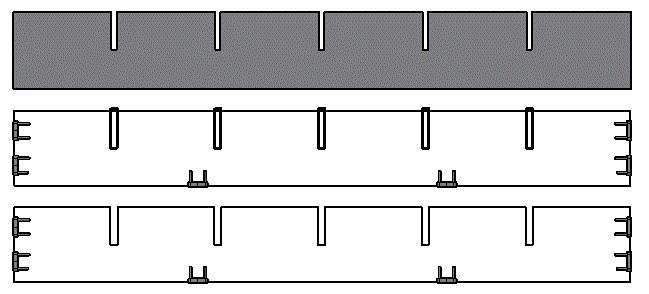
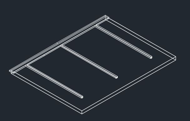
Use Panelization (Y/N) <No>: Suppress Panelization disables the attempt to determine a rectangular outside contour that represents the stock material of the panel object. When Panelization is used (Y), features such as thru dadoes and toekicks are defined when found, to be extracted from the defined outside panel. Without Panelization, all thru features that connect to the geometry determined to be the outside profile, are part of the outside profile. In the following picture, the top object is the model, the middle object is developed with "Use Panelization" set to Yes, and each dado feature is a separate object on a separate layer. In the bottom part, "Use Panelization" is set to No and the dado features are part of the outside shape. It is important to note that Suppress Panelization applies to all thru features that are a part of the Outside Profile.
Create Additional Pocket Geometry (Y/N) <Yes>: If Yes, any Pocket (feature with islands) will create two additional layers: POCKETINSIDE_ and POCKETOUTSIDE_ that correlate with the island (INSIDE) and the outside shape of the Pocket (OUTSIDE).
Dimension Settings:
The settings in this section are used to define layering when the units are metric or standard
Dimension Increment for Inch Mode <0.015625> – Layer names that have depth of cut dimension in the layer name and information in the Cut List that reference material thickness use a depth that is determined by the solid rounded to the nearest increment defined by this setting when in Inch mode. 1/64 (0.015625) of an inch increment is the default. All depths that are displayed are rounded to the nearest 1/64 of an inch. If this is set to 0.0 then all depths are displayed as the actual depth of the solid.
Dimension Increment for Metric Mode <0.0100> – Layer names that have depth of cut dimension in the layer name and information in the Cut List that reference material thickness use a depth that is determined by the solid rounded to the nearest increment defined by this setting when in Metric mode. 1/10 (0.01) of a millimeter increment is the default. All depths that are displayed are rounded to the nearest 1/10 of a millimeter. If this is set to 0.0 then all depths are displayed as the actual depth of the solid.
Slot Settings:
The settings in this section are used when a Slot feature is found when running Solid-CIM
Maximum Slot Width to be considered a Slot <1.0000>: Any Slot feature that has a width greater than this value will be a CutOut. If you need all Slot type features to always be CutOut than set this value to zero.
Extension distance of Slot past edge of part <0.2500>: This value will extend the length of the Slot past the edge of the part at the distance entered for this setting. This setting is not applied to the CutOut polyline described in the "Use Panelization" setting below.
Hole Settings:
Include Thru in Layer Name (Y/N) <Yes> – A circular hole with a diameter that is equal to less then the value defined in the setting 'Maximum Diameter to be considered a Hole' and is analyzed to go through the part will have the designation of THRU in the layer name, i.e. Hole 0.2500_THRU
Include Depth in Layer Name (Y/N) <No> – A circular hole with a diameter that is equal to less then the value defined in the setting 'Maximum Diameter to be considered a Hole' and is analyzed to go through the part will have the designation of the thickness in the layer name, i.e. Hole 0.2500_0.7500
Note: If both 'Include Thru in Layer Name' and 'Include Depth in Layer Name' are selected, the resulting layer will include both the THRU designation and the thickness of the feature, i.e. Hole_0.2500_THRU_0.7500
Maximum Diameter to be considered a Hole <1.3750>: A circular hole with a diameter greater than this value will be a CutOut or Pocket. A diameter equal to or less than this value will be a Drill feature.
Other:
Note: All cutout geometry options will default Panelization to be activated.
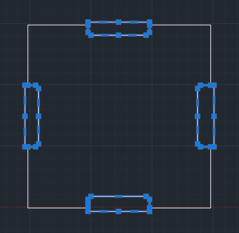
Create Closed Cutout Geometry
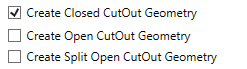
By selecting this option, Solid-CIM 3D will create CutOut geometry as a closed shape.
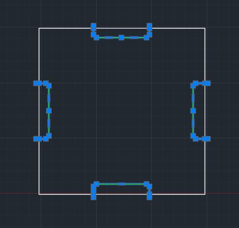
Create Open Cutout Geometry
By selecting this option, Solid-CIM 3D will create CutOut geometry as an open shape with it extending past the edge of the part by the setting of 'Extension Distance of CutOut past edge(s) of part'.
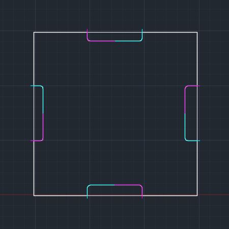
Create Split Open Cutout Geometry
By selecting this option, Solid-CIM 3D will create CutOut geometry as two (2) open shape features with it extending past the edge of the part by the setting of 'Extension Distance of CutOut past edge(s) of part'. The shapes will intersect at the midpoint of the part cutout feature.
Include Width and Radius in CutOut Layers:
By selecting this option, when Solid-CIM 3D identifies a CutOut or PktCutOut, it will check for the narrowest feature and the minimum radius of a Cutout or PktCutOut feature. This information will be included in the layer name to allow for proper cutting knowledge selection.
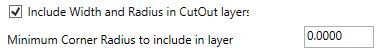
'Minimum Corner Radius to Include in layer' defines the smallest radius that you want this option to identify.
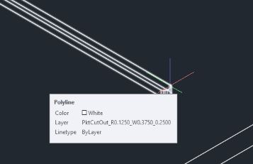
Without the feature checked a sample layer name would be PktCutOut_0.2500 for the above feature. With this option checked the resulting layer would be PktCutOut_R0.1250_W0.3750_0.2500
R - Minimum Radius found in the feature
W - Minimum Width found in the feature
Extension distance of Cutout past edge(s) of part <0.1000>: Any feature determined to be a CutOut (includes Dado and Rabbet features that are large enough in width to be consider a CutOut) will be extended this distance at all locations that align with the OutSide shape.

