|
|

|

|
|||
|
|
|
|
Solid-CIM 3D provides for the definition of Rounded Features. A Rounded Feature is a curved edge that requires the use of a round or ball tool to cut the edge contour. These features are an extension of the basic definition of Solid-CIM 3D features. Typically, a standard straight edge produces a standard CutOut feature with the depth of the feature. An external rounded edge produces a CutOut/Profile feature with the radius of the rounded edge and the extension of a RND. An internal rounded edge produces a feature with the extension of BALL with the radius of the edge. A straight edge would produce a CutOut_0.5000 feature and an external curved edge would produce a CutOut_0.1250_RND_0.1250. The extension of RND_0.1250 indicates that it requires a round tool with a radius of 0.125 to cut the external edge contour.
The samples mentioned in this portion of the Solid-CIM 3D manual can be downloaded here: Solid-CIM 3D Sample Drawings
Fundamentals
The following terms and descriptions outline the basic concept of a feature’s properties.
Direction – All features are assumed to be defined in the Counter-Clockwise direction
CutOut – Direction places the material to the right of the tool
Profile – Direction places the material to the left of the tool
OutSide – Direction places the material to the left of the tool
RND – designates a Round tool is required with the appropriate radius offset
BALL – designates a Ball tool with the feature contour defined as a Center-Line cut. No radius offset.
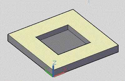
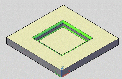
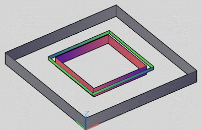
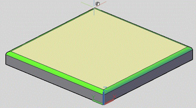
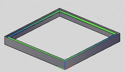
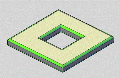
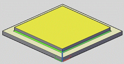
Straight Edge Pocket |
Straight CutOut and OutSide |
Example1.dwg |
|
|
The top highlighted face has 2 loops, a pocket cut out and the outside. The depth of each is the depth determined at all the points along the edge (loop). PktCutOut_0.7500 and OutSide_1.0000 |
|
|
|
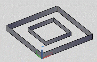
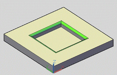
Top External Round Pocket |
Round CutOut, CutOut and OutSide |
Example2.dwg |
|
|
The top highlighted face has 2 loops, an external rounded edge and the outside. The bottom face has 1 loop, the pocket cut out. The PktCutOut_0.7500 has the total depth of the pocket. This feature follows the bottom edge.
The CutOut_0.2500_Rnd_0.2500 has the depth of the radius. This feature follows the top edge. |
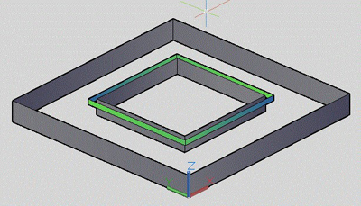
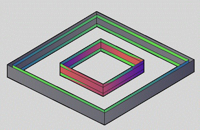
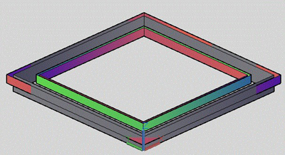
Top External Round, Bottom Internal Round Pocket |
Round CutOut, Pocket CutOut with Ball and OutSide |
Example3.dwg |
|
|
The top highlighted face has 2 loops, a external rounded edge and the outside. The bottom face has 1 loop, the pocket cut out with an internal round. The PktCutOut_0.7500_BALL_0.1250 has the total depth of the pocket. This feature follows the bottom edge as a Center-Line cut. The CutOut_0.2500_Rnd_0.2500 has the depth of the radius. This feature follows the top edge. |
|
|
|
Top External Round |
Round Profile and OutSide |
Example4.dwg |
|
|
The top highlighted face has a external rounded edge that is the outside of the part. Two features are developed. The OutSide and the Profile_0.2500_RND_0.2500 that represents the external round edge. |
|
|
|
Top/Bottom External Rounded |
Round Profiles and CutOuts |
Example5.dwg |
|
|
Part is rounded on all edges, top and bottom. An OutSide and CutOut is developed along with all the CutOut Rounds and Profile Rounds to handle the rounded edges. |
|
|
|
Top Partial External Rounded |
Open Round Profile and CutOut |
Example6.dwg |
|
|
Part has rounded edges only on a couple of edges of the top contour. An open Profile feature is developed in a CCW direction. |
|
|
|
Protruding (Boss) Feature |
Pocket, Profile & OutSide Features |
Example7.dwg |
|
|
The Profile defines the internal Ball feature using a Center-Line Cut. The Pocket defines the feature around the Boss. Profile_0.5000_Ball_0.1250 Pocket_0.5000 OutSide_1.0000 |
Limitations
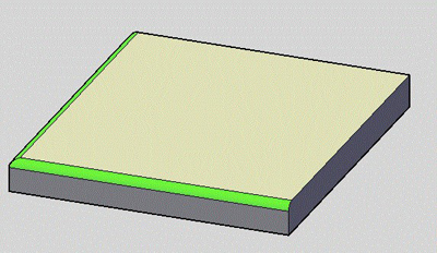
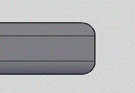
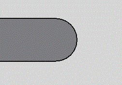
There is a limitation in the geometric configuration of a solid that has rounded edges. The rounded edges should not form a tangent point between two parallel edges on the side of the solid. There must be a vertical definition all the way around the solid that provides a basis for the outside profile.
The pictures below represent side views of a solid. The left view has a straight vertical definition of the side of the solid and can be processed. The right view has a tangent definition of the side of the solid and can’t be processed.
Correct Side Definition |
Wrong Side Definition |
|
|
Example Parts
The following drawings are provided with this document. These represent test cases used in the development of these new features. Each contains different aspects of the concepts described above, some more complex than others.
The samples mentioned in this portion of the Solid-CIM 3D manual can be downloaded here: Solid-CIM 3D Sample Drawings
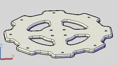
Rounded_Part_1.dwg |
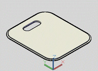
Rounded_Part_2.dwg |
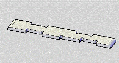
Rounded_Part_3.dwg |
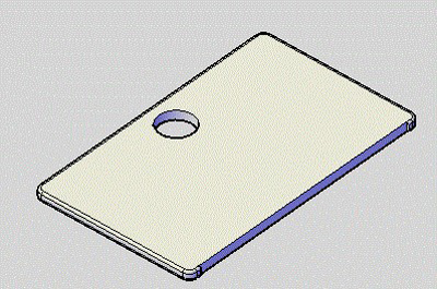
Rounded_Part_4.dwg |