![]()
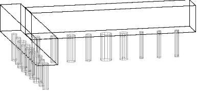
The Pattern Recognition cycle examines the drill holes on your part and the configuration of your drilling head(s) to determine the most efficient means of boring the selected holes. In order to use this function properly, the configuration of your drill heads must be set before you attempt to use this cycle. (See Note below.) Once configured, pick Pattern Recognition from the Cycle menu, choose Cut, and then select the holes to be bored. Pattern Recognition will load into memory, determine the most efficient route, and then proceed to bore the holes. The lead spindle in the group will have the tool path displayed on the screen; the others in the group will change colors to show they have been processed. The gang drill drawing will be provided to you by CIM-Tech following the specifications of your machine tool. Drill holes processed with Pattern Recognition need not be Geoshaped, and should be given thickness equal to their depth (negative Z value).
Note: The size of the holes on your gang drill drawing in your machine-specific default drawing MUST BE THE SAME SIZE as the holes in your current drawing for Pattern Recognition to work. You do not need to add any tool numbers in the Control Panel, as Pattern Recognition will find the tools it needs and add them automatically.
Pattern Recognition - Tolerance Variable
For Pattern Recognition to work properly, the diameter of the holes in your current drawing must be the same size as the holes on your gang drill drawing in your machine-specific default drawing (which is loaded into your current drawing upon loading Router-CIM). There is a tolerance built into the system, for the diameter of the holes, that is set to 0.05. Under normal circumstances this need not be changed. But, if you have tools of a similar size (i.e. within .05 in radius or diameter) then Pattern Recognition may choose the wrong tools to complete its boring operation. Generally, if you are using all inch or all metric this will not be a problem.
Example: There are six drills on the gang drill with 5mm diameter drills in them. The part has both 5mm and 0.125 diameter holes in it. The difference between these two diameters is within the 0.05 tolerance, so Pattern Recognition will see them all as one size. Therefore, all six drills will drop and drill all six holes and all hole diameters will be 5mm, which is incorrect.

If it becomes necessary to change the tolerance (as in the example above), follow these steps:
1. 1. At the command line, type NCVAR and select Geometric.
2. 2. Select Add, type in *pat_fuzz* and press Enter.
3. 3. Enter a value between 0.007 and 0.05 and press Enter, then click Yes, then Exit. Reload Router-CIM, and the new variable will now be part of your system. You do not have to enter it again.
Note: DO NOT enter a value of less than 0.007 in this variable.
The HD Command
The HD command is used to change the diameter of all circles in a drawing. When you type HD at the Command prompt, you are asked to ENTER EXISTING DIA and ENTER NEW DIA. This changes all circles in the current drawing from the existing diameter to a new diameter. This command only changes circles that have not been Geoshaped.
The HD command works differently if you issue the PH command first. The HD command will ask you to SELECT EXISTING HOLE, then ENTER NEW DIA. This changes all circles in the current drawing that have the same diameter as the picked circle to the new diameter.