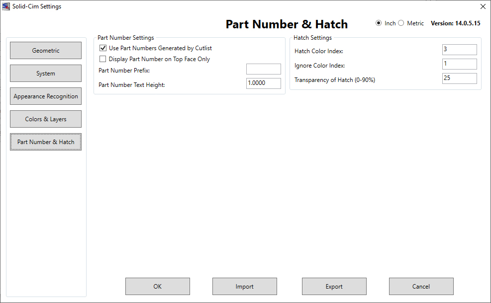
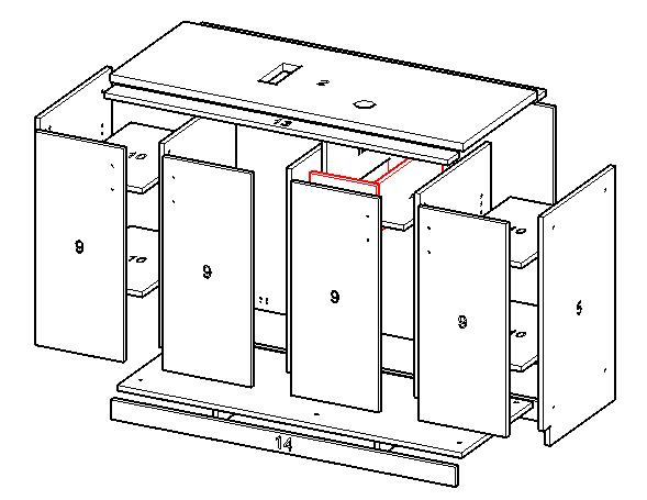
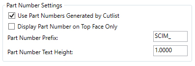
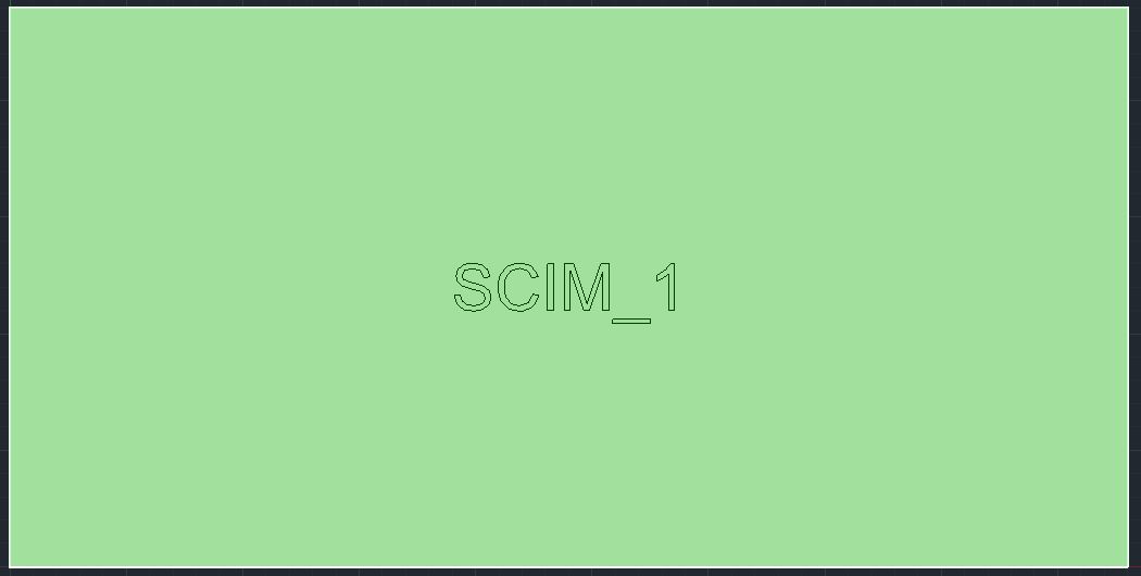
| Part numbers are generated when the Cut List is developed. A Cut List can be developed by selecting the CutList option in SCIM or by the Export option in SCIM. Any time the Cut List is developed, part numbers are placed in each part definition. Using the CutList option will display the Cut List and running the command SCIM again will return the display to the graphics of the assembly with part numbers. Part numbers are located on the top and bottom sides of a part. A part number is a member of the Solid-CIM 3D part group definition. The location is normally in the center of the part. If there are Cut Outs in the part, a location is determined elsewhere on the part nearest the center. A part number is an AutoCAD attributed Insert. The attribute is annotative and supports Viewports annotation. Default annotation values assigned to a part number are 1:1, 1:2, 1:4, 1:5, 1:8, 1:10. Annotative objects can be assigned additional values through the use of AutoCAD’s Annotate commands. Part numbers are placed on the _ScimPartNumbers layer. Control of the display of part numbers is handled by turning on or off this layer. Since a part number appears on both sides of a Solid-CIM 3D part, Visual Styles that are transparent will show both representations of the part number. |


