Geometric Settings
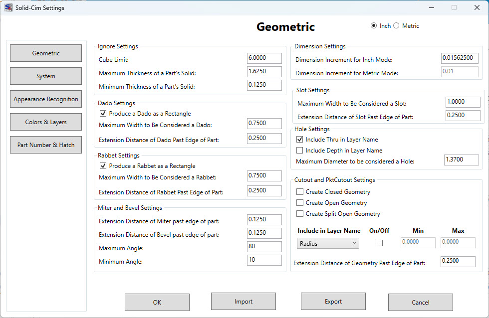
The settings below are represented in Inches.
Ignore Settings:
The settings in this section are used to define what Solid-CIM will include and ignore when processing
Cube Limit <6.00>: Any solid found that fits totally inside a box with the measurement of “Cube Limit” will be ignored by Solid-CIM 3D and placed on the ignored layer. This filters outs solids that are hardware objects and not parts to be cut.
Maximum thickness of a part's solid <1.6250>: All curved parts are ignored and any flat parts that have a thickness greater than this “Maximum” value. A solid is lay downed flat and the thickness is determined by the solid’s extents in Z.
Minimum thickness of a part's solid <0.1250>: Same as described in “Maximum” except this is for the “Minimum” thickness. Any thickness less than this value is ignored.
Dado Settings:
The settings in this section are used when a Dado feature is found when running Solid-CIM
Produce a Dado as a rectangle [DadoRec] (Y/N) <Yes>: Yes = the Dado will be a rectangle around the Dado feature on the DadoRec layer. No = the Dado will be a straight polyline true the center of the Dado feature on the DadoLine layer.
Maximum Dado Width to be considered a Dado <0.7500>: Any Dado feature that has a width greater than this value will be a CutOut. If you need all Dado type features to always be CutOut than set this value to zero.
Extension distance of Dado past edge of part <0.2500>: This value will extend the length of the Dado past the edge of the part at the distance entered for this setting. This setting will be applied to the DadoRec and DadoLine polylines described in setting #5. This setting is not applied to the CutOut polyline described in setting #6.
Rabbet Settings:
The settings in this section are used when a Rabbet feature is found when running Solid-CIM
Produce a Rabbet as a rectangle [RabbetRec] (Y/N) <Yes>: Yes = the Rabbet will be a rectangle around the Rabbet feature on the RabbetRec layer. No = the Rabbet will be a straight polyline along the material side of the Rabbet feature on the RabbetLine layer.
Maximum Rabbet Width to be considered a Rabbet <0.7500>: Any Rabbet feature that has a width greater than this value will be a CutOut. If you need all Rabbet type features to always be CutOut than set this value to zero.
Extension distance of Rabbet past edge of part <0.2500>: This value will extend the length and width of the Rabbet past the edges of the part at the distance entered for this setting. This setting will be applied to the RabbetRec and RabbetLine polylines described in setting #8. This setting is not applied to the CutOut polyline described in setting #9.
Miter and Bevel Settings:
The settings in this section are used when a Miter or Bevel feature is found when running Solid-CIM
Extension distance of Miter past edge of part <0.1250>: This value will extend the length of the Miter past the edges of the part at the distance entered for this setting.
Extension distance of Bevel past edge of part <0.1250>: This value will extend the length of the Bevel past the edges of the part at the distance entered for this setting.
Maximum Angle <80>: Any Miter/Bevel feature that has an angle greater than this value will not be recognized as a Miter or Bevel.
Minimum Angle <10>: Any Miter/Bevel feature that has an angle less than this value will not be recognized as a Miter of Bevel.
Dimension Settings:
The settings in this section are used to define layering when the units are metric or standard
Dimension Increment for Inch Mode <0.015625> – Layer names that have depth of cut dimension in the layer name and information in the Cut List that reference material thickness use a depth that is determined by the solid rounded to the nearest increment defined by this setting when in Inch mode. 1/64 (0.015625) of an inch increment is the default. All depths that are displayed are rounded to the nearest 1/64 of an inch. If this is set to 0.0 then all depths are displayed as the actual depth of the solid.
Dimension Increment for Metric Mode <0.0100> – Layer names that have depth of cut dimension in the layer name and information in the Cut List that reference material thickness use a depth that is determined by the solid rounded to the nearest increment defined by this setting when in Metric mode. 1/10 (0.01) of a millimeter increment is the default. All depths that are displayed are rounded to the nearest 1/10 of a millimeter. If this is set to 0.0 then all depths are displayed as the actual depth of the solid.
Slot Settings:
The settings in this section are used when a Slot feature is found when running Solid-CIM
Maximum Slot Width to be considered a Slot <1.0000>: Any Slot feature that has a width greater than this value will be a CutOut. If you need all Slot type features to always be CutOut than set this value to zero.
Extension distance of Slot past edge of part <0.2500>: This value will extend the length of the Slot past the edge of the part at the distance entered for this setting. This setting is not applied to the CutOut polyline described in the "Use Panelization" setting below.
Hole Settings:
Include Thru in Layer Name (Y/N) <Yes> – A circular hole with a diameter that is equal to less then the value defined in the setting 'Maximum Diameter to be considered a Hole' and is analyzed to go through the part will have the designation of THRU in the layer name, i.e. Hole 0.2500_THRU
Include Depth in Layer Name (Y/N) <No> – A circular hole with a diameter that is equal to less then the value defined in the setting 'Maximum Diameter to be considered a Hole' and is analyzed to go through the part will have the designation of the thickness in the layer name, i.e. Hole 0.2500_0.7500
Note: If both 'Include Thru in Layer Name' and 'Include Depth in Layer Name' are selected, the resulting layer will include both the THRU designation and the thickness of the feature, i.e. Hole_0.2500_THRU_0.7500
Maximum Diameter to be considered a Hole <1.3750>: A circular hole with a diameter greater than this value will be a CutOut or Pocket. A diameter equal to or less than this value will be a Drill feature.
Cutout and PktCutout Settings:
Note: All cutout geometry options will default Panelization to be activated.
Create Closed Cutout Geometry
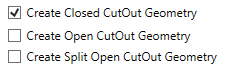
By selecting this option, Solid-CIM 3D will create CutOut geometry as a closed shape.
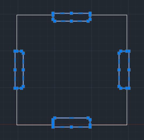
Create Open Cutout Geometry
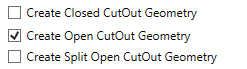
By selecting this option, Solid-CIM 3D will create CutOut geometry as an open shape with it extending past the edge of the part by the setting of 'Extension Distance of CutOut past edge(s) of part'.
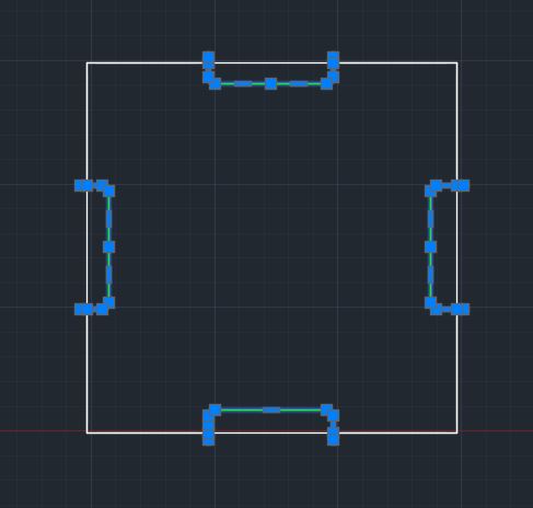
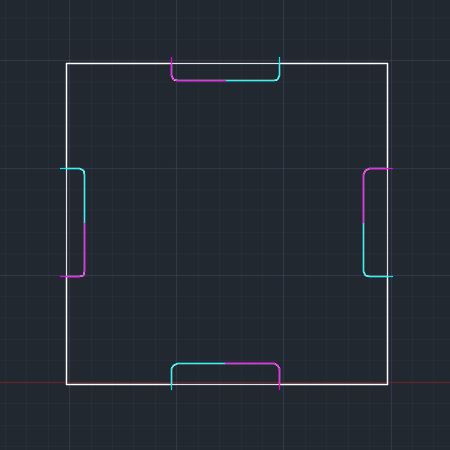
Create Split Open Cutout Geometry
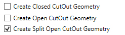
By selecting this option, Solid-CIM 3D will create CutOut geometry as two (2) open shape features with it extending past the edge of the part by the setting of 'Extension Distance of CutOut past edge(s) of part'. The shapes will intersect at the midpoint of the part cutout feature.
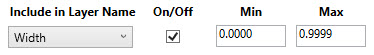
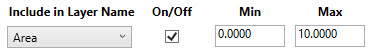
Include in Layer Name:
By selecting this option, when Solid-CIM 3D identifies a CutOut or PktCutOut, it will approximate the narrowest feature, minimum radius and/or area of a Cutout or PktCutOut feature. This information will be included in the layer name to allow for proper cutting knowledge selection.
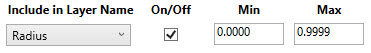
| R - Minimum Radius found in the feature |
| RMIN if Minimum value found |
| RMAX if Maximum value found |
| W - Minimum Width found in the feature |
| WMIN if Minimum value found |
| WMAX if Maximum value found |
| AMIN if Minimum value found |
| AMAX if Maximum value found |
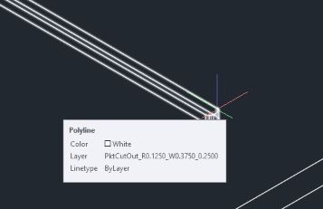
Without the feature checked a sample layer name would be PktCutOut_0.2500 for the above feature. With this option checked the resulting layer would be PktCutOut_R0.1250_W0.3750_0.2500
Extension distance of Cutout past edge(s) of part <0.2500>: Any feature determined to be a CutOut (includes Dado and Rabbet features that are large enough in width to be consider a CutOut) will be extended this distance at all locations that align with the OutSide shape.

