System Settings
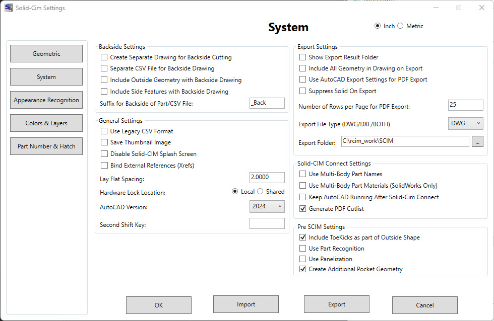
The settings below are unit-less except for the Lay Flat Spacing which is in Inches or Millimeters depending on the MEASUREMENT setting in AutoCAD.
Backside Settings:
The settings in this section are used when a Backside feature is found when running Solid-CIM
Create Separate Drawing for BackSide Cutting (Y/N) <No>: If Yes, a separate drawing is made for all back side cutting. The drawing name has a _Back added to the end of the drawing name. If No (the default), all back side cuts layers are renamed with a _Back added to the end of the layer name. Both methods always position all cuts at locations relative to Z zero with WCS reference.
Create Separate CSV File for BackSide Drawing (Y/N) <No>: If Yes, a separate CSV file is made for all back side drawings. The CSV file name has a _Back added to the end of the name if option Yes if chosen
Include Outside Geometry with BackSide Drawing (Y/N) <No>: If Yes, the Outside geometry will be included in the BackSide Drawing file on a layer starting with "BACK_" followed by the thickness of the part.
Include Side Features with BackSide Drawing (Y/N) <No>: If Yes, any horizontal features will be included in the BackSide Drawing file with the appropriate horizontal layer name.
Suffix for BackSide of Part/CSV File <_BACK>: If a Back Side feature is found, and a separate CSV or drawing is created than the suffix added to that file name will match what is typed in this field
General Settings:
Use Legacy CSV Format (Y/N) <No>: When exporting the results of Solid-CIM, if true, the output CSV file from Solid-CIM 3D will match the legacy format from previous versions. More information can be found in the 'Export Parts' section of the manual.
Save Thumbnail Image (Y/N) <No>: This allows a thumbnail image to be saved with the created part file so that a preview can be seen prior to opening.
Disable Solid-CIM Splash Screen (Y/N) <No> - When AutoCAD is opening a Solid-CIM Splash Screen is displayed in order to show that certain functions loaded correctly for Solid-CIM.
Bind External References (Xrefs) (Y/N) <No> - When the Solid-CIM process is run, external references (Xrefs) will be ignored. If this option is checked, Xrefs will be inserted and any 3D solid included with the Xref will be processed by Solid-CIM
LayOut Spacing <2.00>: The spacing between parts for the Lay Down option.
Hardware Lock Location? (Local or Shared) <Local> - By setting this to Local means that the Router-CIM/Solid-CIM hardware lock is plugged directly into the computer using the software. If the hardware lock is located on a network then this should be set to Shared in order for the software to locate the lock.
AutoCAD Version - Shows the installed versions of AutoCAD that are compatible with the installed Solid-CIM 3D version.
Second Shift Key - This field is for custom software activation. Custom software will receive a code to enter into this field to activate.
Export Settings:
The settings in this section are used when exporting the results from Solid-CIM
Show Results Folder (Y/N) <No>: This option will show the Explorer window of the result folder produced by Solid-CIM 3D Connect. This can be used to validate the result files. Also, it can be used to launch Router-CIM Automation by right-click on the .csv file and open the file using Router-CIM Automation.
Include all geometry in drawing on Export (Y/N) <No>: If True, there is only one part being exported then it will export all the geometry that is currently in the drawing such as additional geometry that may have been added after the part was laid down. This only applies to single part exports.
Use AutoCAD Export Settings for Export PDF (Y/N) <No> – Export PDF can be controlled by the Export Settings available in AutoCAD. The AutoCAD command that controls these settings is EXPORTSETTINGS. There are a variety of selections you can define. If this setting is Yes, the Export PDF will use the values you have defined in the EXPORTSETTINGS command. A common selection is to determine if the layout is either Portrait or Landscape when developing the PDF file.
WARNING – IMPORTANT! – Leave this setting as 'No' unless you are sure that your Export Settings for Page Setup Override are correct and valid.
Export PDF is a script that uses AutoCAD commands. All responses to these commands must be accurate and correct. Any mistakes will stop the script and the PDF file will not be produced. You will see that the Export PDF process has been interrupted. To ensure that your Page Setup Overrides are correct run the EXPORTSETTINGS command and select the Page setup option.
If you see a warning like this: 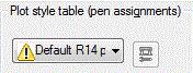 you should set this Plot style table to None selection. Or you should set this Solid-CIM 3D option to No to protect the Export PDF from errors.
Suppress Solid on Export (Y/N) <No> – By default, the resulting file that Solid-CIM 3D creates will include the 3D solid of the analyzed part. If you do not want the 3D solid on export, select this option.
Number of Rows per Page for Export PDF <50> – During Export PDF the Cut List is exported to PDF file(s). The number of rows per page determines the limit of rows to be printed per PDF file. The default is 50 rows per page. Each page repeats the header columns to aid in understanding of the information.
Export File Type <DWG> – When exporting the results of Solid-CIM individual part files will be created. This option allows you to choose if the files created are DWG, DXF, or Both DWG and DXF.
Export Folder <C:\rcim_work\SCIM> – When exporting the results of Solid-CIM, use the button to define the parent folder that you would like Solid-CIM 3D to export the results to.
Solid-CIM Connect Settings:
The settings in this section are used when the Solid-CIM Connect feature is used to export out of other 3D modeling software when applicable.
Use Multi-body Part Names <No>: If Yes, the name of the part file that Solid-CIM 3D creates will be the name of the identified solid body in a multi-body solid single part.
Use Multi-body Part Materials (SOLIDWORKS Only) <No>: If Yes, Solid-CIM 3D will identify the material attached on a multi-body solid part according to the 3D modeling software.
Keep AutoCAD Running After Solid-CIM Connect (Y/N) <No>: This option allows for AutoCAD to stay running after the Solid-CIM 3D Connect process. The state of Solid-CIM 3D at this time is a view of all the Cut List tables that can be exported as PDF files. Solid-CIM 3D Connect does not export PDF files during the automatic process. However, there is the command SCIMPDF that can be used to add the Cut List tables as PDF files to the exported data produced by Solid-CIM 3D Connect. By persisting AutoCAD and using the SCIMPDF command in AutoCAD while the Cut List tables are in view, the PDF files will be created. Also, Solid-CIM 3D is available for any validation activities that may be necessary.
Generate PDF Cutlist <Yes>: When selected, this will create the PDF of the SCIM cut list when you use the Solid-CIM Connect feature.
Pre-SCIM Settings:
Include Toekicks as part of outside shape (Y/N) <Yes>: If Yes, any ToeKick features with be removed and the OutSide shape will incorporate these features into the OutSide shape definition.
Use Part Recognition (Y/N) <No> – Part Recognition is the very first process in Solid-CIM 3D. Part Recognition is the process of finding all the solids that are identical in physical characteristics and represent copies of the same part. This process is used to define the quantity of each individual part. There are unique situations where two parts that appear to be the same in Part Recognition are actually two different parts. By not using Part Recognition ALL solids are considered individual parts even if there are identical in physical characteristics. This should only be used in very unique situations.
This option can be used on an individual part basis. Set this option to the desired settings, select only those solids you want to process in Solid-CIM 3D and then reset this option and select all the other solids using Solid-CIM 3D.
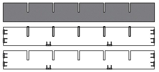
Use Panelization (Y/N) <No>: Suppress Panelization disables the attempt to determine a rectangular outside contour that represents the stock material of the panel object. When Panelization is used (Y), features such as thru dadoes and toekicks are defined when found, to be extracted from the defined outside panel. Without Panelization, all thru features that connect to the geometry determined to be the outside profile, are part of the outside profile. In the following picture, the top object is the model, the middle object is developed with "Use Panelization" set to Yes, and each dado feature is a separate object on a separate layer. In the bottom part, "Use Panelization" is set to No and the dado features are part of the outside shape. It is important to note that Suppress Panelization applies to all thru features that are a part of the Outside Profile.
Create Additional Pocket Geometry (Y/N) <Yes>: If Yes, any Pocket (feature with islands) will create two additional layers: POCKETINSIDE_ and POCKETOUTSIDE_ that correlate with the island (INSIDE) and the outside shape of the Pocket (OUTSIDE).

