|
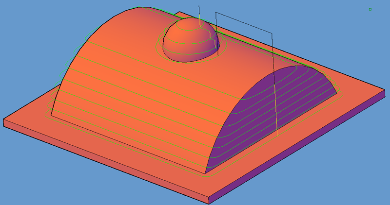
Nurbs CCW XY is a horizontal slicing cycle. Horizontal slicing will produce a tool path in the XY plane at each Z level, slicing horizontally instead of vertically in either X or Y. This is useful for some roughing and finishing operations where vertical slicing leaves an undesirable finish.
The tool path can be controlled in the Z plane between passes by setting the Z Level Completion option to either Yes or No.
Leads used on this cycle are linear by default with a straight plunge to the cut Z level, however, checking the leads option will allow arc lead-in and lead-out moves to be created for the beginning and end of the tool path. Each slice in between will still have a plunge move in Z. |

Shown is a tool path created with the default settings of the NURBS CCW XY cycle. Similar results can be obtained by selecting the cycle and simply pressing the cut button and selecting the solid model. When prompted at the command line:
Enter Surface Tolerance <0.00050000>:
Enter .005
Enter Surface Tolerance <0.00050000>: .003
You should see the same tool path as the picture above. The surface tolerance is the amount of deviation allowed for the tool path to follow the surface of the part as it breaks the moves up into small line segments for each pass. The smaller this number is, the more closely the tool path will follow the part contours, but the segments of the cut will be smaller, and thus produce more NC Code.
**Changing values in the cycle parameters may yield unexpected results with some settings or on some geometry. Examine the toolpath and NC Code carefully before running your machine tool if you change these default settings.