Spiral Pocketing is a method used to have the tool follow the contour of the part as it removes material. The cycle will create a tool path that makes offsets of the shape you are cutting, spaced according to how you set up the cut spacing.
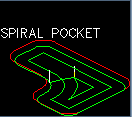
This is an example of a Spiral Pocket tool path.
The difference between linear and spiral pocketing is simple in the fact that spiral pocketing will create offsets of the shape that is being pocketed, where linear pocketing will simply move the tool back and forth across the shape until the shape is cleared. There are advantages to both types and those will be discussed later in more detail.
Spiral pocketing has options to allow island clean up passes and also, like linear pocketing, has the ability to control the amount of the offset for each pass, including the finish pass.
The following is a quick overview of the cycle features.
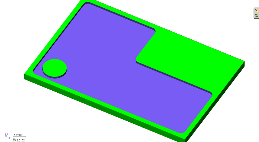
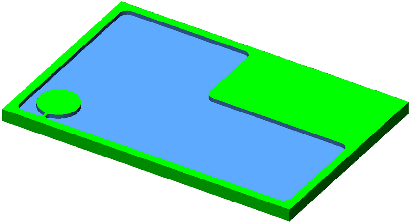
In order to pocket a simple shape like this you will need to have a way to finish the outside of the shape and also the island.
Open the SPIRAL_POCKET_1.dwg file. You can download it here.
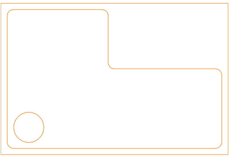
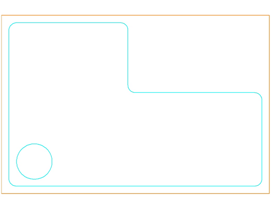
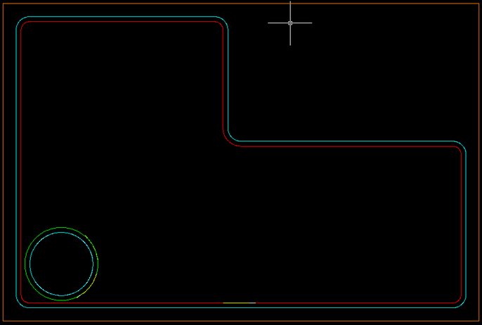
Geoshape the two inside shapes that will define the pocket. The drawing should look like this:
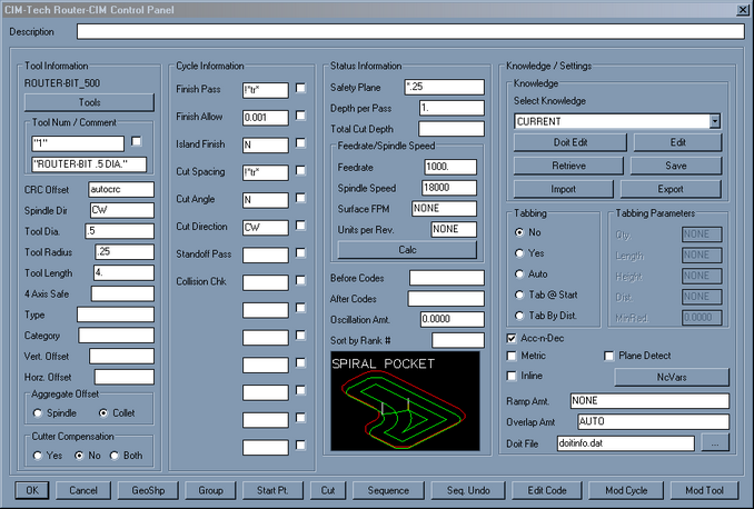
Selecting the Spiral Pocketing cycle, you will see the defaults like this:
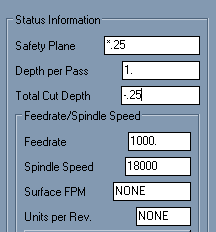
Set the cut depth to -.25 like this:
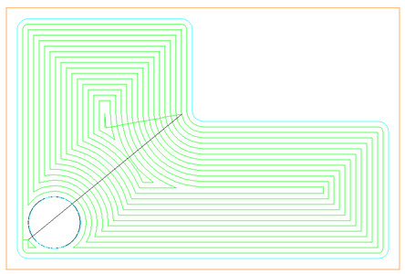
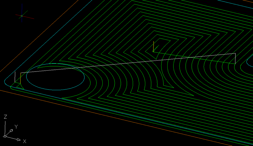
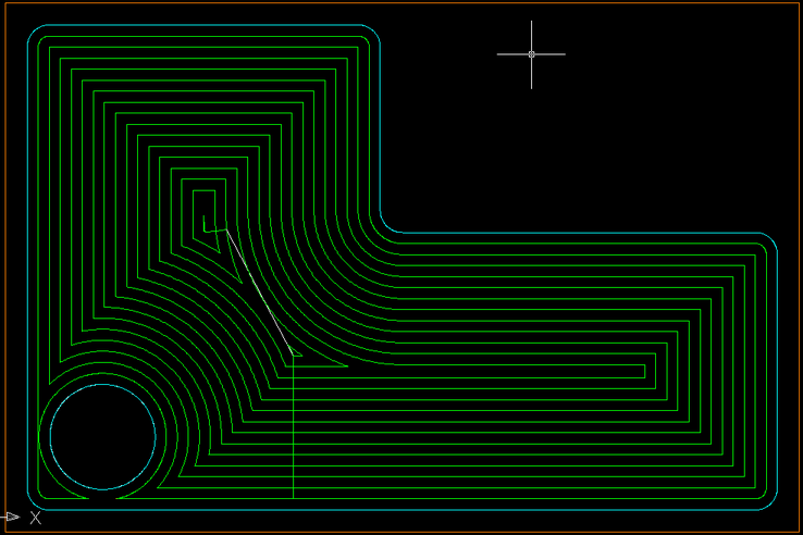
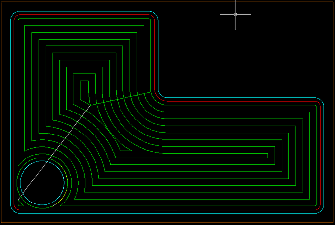
Then select CUT, and select both the inside shape and the circle shape of the pocket, you will get the following results:
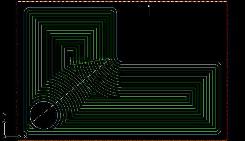
What you can notice in this example is that the tool must lift up from one cut area and move over to an area that it was not able to finish by offsetting the shape that it was cutting. This pick up allowed the tool to move over to an area that was not cut and make more tool paths to finish the areas it could cut.
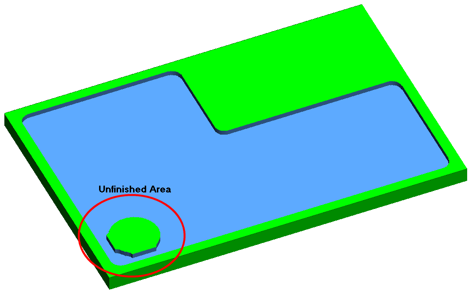
Still, even though the tool lifted up, and moved to the uncut area, the parameters of this cut leave material in the shape, causing the real part to be unfinished. The following check of the code from this tool path shows the area by the circle is not really finished.
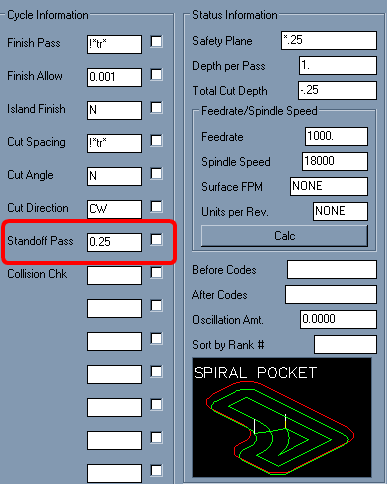
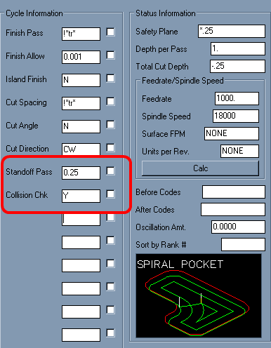
If you look back on the tool path that was created, you can see that there was no path for the tool in the areas around the circle that remain uncut. This can be caused by a few factors, but the main factor is that we did not specify the cut parameters to allow a Standoff Pass around the island. If we change the cycle parameters to allow a Standoff Pass of 0.25 (the radius of our current tool) like this:
Then erase the current tool path and make a CUT with the current parameters, we should see a result like this:
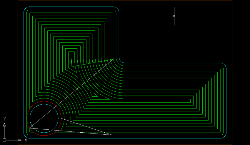
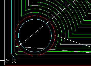
This clearly shows a separate Standoff Pass (in RED) around the island at the bottom. However if you look at that closely, you will see that this Standoff Pass could gouge the edge of the finished pocket on the bottom. Look at this area closer:
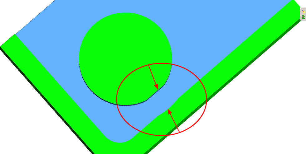
If you were to check this code in MCU, you would see a small gouge in the bottom of the shape like this:
This gouge was created because we forced a Standoff Pass and did not have Router-CIM check the tool path for a possible Collision with the shapes we were selecting.
Erase the current tool path and then change you knowledge setup to look like this:
Now you are allowing Router-CIM to make a Standoff Pass, if it can, after checking the tool path for a Collision with the shapes you are cutting. If a collision is detected, then that part of the tool path is not created.
Make a CUT with these parameters and your tool path should look like this:
This is closer to what you want, but you can still see that the island cannot have a total finish pass. This is because the tool that is in use (in this case a 0.5" Router-Bit) cannot fit between the island and the finished edge of the pocket.
Verifying the code from this drawing shows the following result:
Remember that pocketing is a Roughing cycle, and that there are times when you will want a finish pass around your shapes to make sure they are the right size and shape.
Setting up a smaller diameter tool to cut around the circle shape is one way to make the circle cut properly.
Using a smaller diameter tool for the entire pocket would also be a way to get the pocket cut properly. However, a smaller diameter tool will mean more passes, and perhaps more cycle time.
Roughing and Finishing.
Using a larger diameter tool to remove most of the pocket and then a smaller diameter tool to do clean up is sometimes a more efficient way to pocket. A larger tool can remove the bulk of the material and leave the areas where a finish tool can size the pocket correctly.
For instance, setting up your initial pocket cut to use a 3/4" cutter as the rougher, like the following screen:
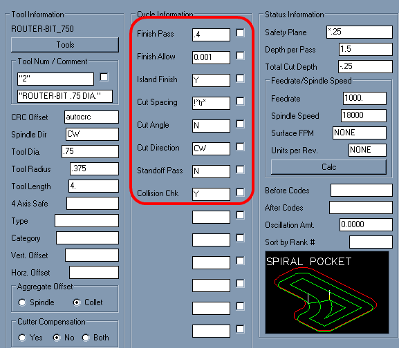
Setting the Finish Pass to .4 will keep the tool .4" away from the edge of the shapes we are cutting. That means the pocket will need to be cut with a finish tool to remove the extra 0.025" left around the edges. It will however remove most of the material and in fewer passes than the .5" tool did.
Using a smaller diameter tool and setting up an Outside cut around the circle and an inside cut around the edge of the shape, like this:
and then Sequencing all three cuts together ( the pocket cut, and both separate finish cuts) like this:
will create the correct finished part. When sequenced and verified, the part looks like this: