Setting up Drill Interpolation knowledge.
There are two sample cut knowledges in the Drill Interpolation sample drawing. Each of them is designed to show a slightly different configuration to drilling. The first one will make the cuts in one pass in Z, and the second will make the cuts in multiple passes in Z.
DrillInterp1Pass
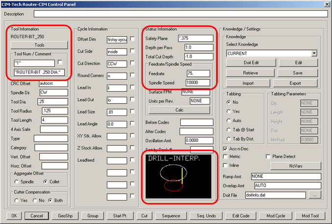
The steps necessary to make Drill Interpolation function are to select a Router-Bit from the tool list, change the cycle to Drill Interpolation and change your Status settings to the variables necessary to cut the hole.
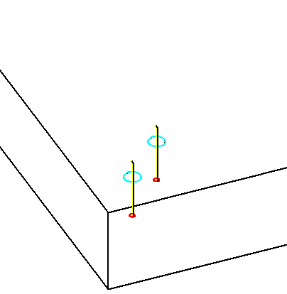
Using these settings will produce cuts that look like this in the drawing:
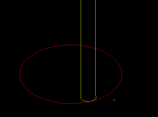
If you zoom close up to the bottom of the cuts, you will see that these tool paths have a small arc lead in and lead out and move the cutter in a circle around the shape to create the hole.
Sequencing the cuts will produce code that looks similar to this:
(ROUTER-BIT .250 DIA.)
G28G91Z0M05
G90T2001M06
T102
M03S10000
G00G17G55X10.916Y.99 <<-- Index to starting location.
G00G43H1Z.375 <<-- Move the cutter to the Safety Plane in Z.
G41D01G01X11.0535F37.5 <<-- Turn on Cutter Radius Compensation (above the part).
Z-1. <<-- Plunge down to the specified cut depth.
G03X11.0635Y1.J.01F75. <<-- Make the small arc Lead In.
I-.0635 <<-- Cut the circle.
X11.0535Y1.01I-.01 <<-- Make the small Lead Out.
G00Z.375 <<-- Raise the cutter back up in Z to the Safety Plane.
G40G00X10.916 <<-- Turn off Cutter Radius Compensation.
X9.916Y1.99 <<-- Index to next starting location.
G41D01G01X10.0535F37.5 <<-- Turn on Cutter Radius Compensation (above the part).
Z-1. <<-- Plunge down to the specified cut depth.
G03X10.0635Y2.J.01F75. <<-- Make the small arc Lead In.
I-.0635 <<-- Cut the circle.
X10.0535Y2.01I-.01 <<-- Make the small Lead Out.
G00Z.375 <<-- Raise the cutter back up in Z to the Safety Plane.
G40G00X9.916 <<-- Turn off Cutter Radius Compensation.
G28G91Z0M5
DrillInterp2Pass
Changing the knowledge to support multiple depths per pass is a simple matter of changing the Depth Per Pass to a value that will allow the tool to cut more than once.
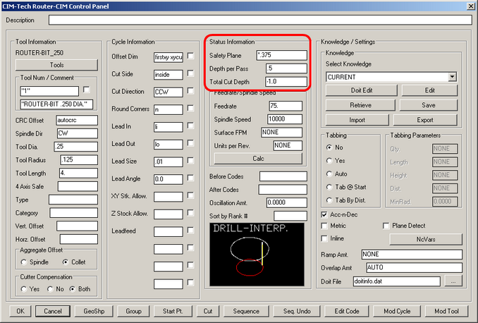
Cutting two more holes with this knowledge will clearly show two passes in Z on each hole.
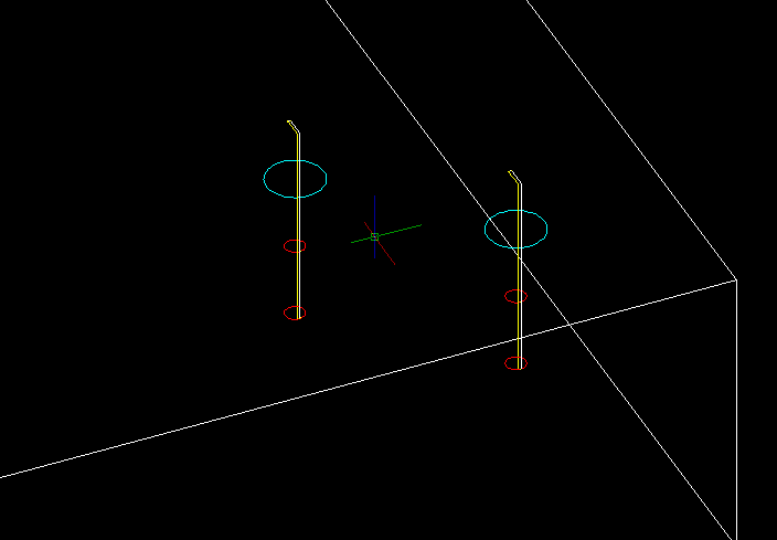
Sequencing these cuts results in the tool leading in to the first depth, cutting the circle and then retracting to the Safety Plane, next plunging to the final depth and cutting the circle and then retracting out of the hole to the Safety Plane, and then moving over to the next hole to start the procedure again.
(ROUTER-BIT .250 DIA.)
G28G91Z0M05
G90T2001M06
T102
M03S10000
G00G17G55X9.916Y9.99 <<-- First Hole Pass 1
G00G43H1Z.375
G41D01G01X10.0535F37.5
Z-.5
G03X10.0635Y10.J.01F75.
I-.0635
X10.0535Y10.01I-.01
G00Z.375
G40G00X9.916
Y9.99
G41D01G01X10.0535F37.5 <<-- First Hole Pass 2
Z-1.
G03X10.0635Y10.J.01F75.
I-.0635
X10.0535Y10.01I-.01
G00Z.375
G40G00X9.916
X10.916Y10.99 <<-- Second Hole Pass 1
G41D01G01X11.0535F37.5
Z-.5
G03X11.0635Y11.J.01F75.
I-.0635
X11.0535Y11.01I-.01
G00Z.375
G40G00X10.916
Y10.99 <<-- Second Hole Pass 2
G41D01G01X11.0535F37.5
Z-1.
G03X11.0635Y11.J.01F75.
I-.0635
X11.0535Y11.01I-.01
G00Z.375
G40G00X10.916
G28G91Z0M5