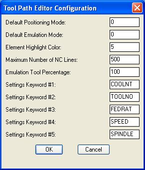
The Sequence Emulator Options Set different modes and values that control the Tool Path Editor

Default Positioning Mode
Positioning Modes: 0 = line/arc, 1 = path, 2 = cut
Line/Arc - positions along a cut by one single motion at a time.
Path - positions along a cut for an entire cut path at a time.
Cut - positions along an entire cut block at a time.
Default Emulation Mode
Emulation Modes: 0 = highlight, 1 = tool drop, 2 = vector
Highlight - draws the object using the Highlight color.
Tool Drop - inserts the tool geometry at intervals along the cut path.
Vector - draws vectors representing the tool alon the cut path.
Element Highlight Color
Highlight Color - a number representing an AutoCAD color. An object is highlighted by redrawing the object using this color.
Maximum Number NC Lines
Maximum of NC Code Lines - a buffer of information is stored in memory in which the editor works on. The size of this work space is determined by the approximate number of NC code lines that would be generated within the work space.
Emulation Tool Percentage
Emulation Tool Percentage - When using Vector or Tool Drop emulation, the spacing between each emulation motion is determined by the percentage of the tool radius.
Settings Keyword #1
A postprocessor command word that will appear in the setting areas when encountered in the sequence.
Settings Keyword #2
A postprocessor command word that will appear in the setting areas when encountered in the sequence.
Settings Keyword #3
A postprocessor command word that will appear in the setting areas when encountered in the sequence.
Settings Keyword #4
A postprocessor command word that will appear in the setting areas when encountered in the sequence.
Settings Keyword #5
A postprocessor command word that will appear in the setting areas when encountered in the sequence.