Linear and Spiral Pocketing have several parameters that can be used to modify the results of the tool paths. Some of these were described in the previous sections on Linear and Spiral Pocketing.
The parameters available are listed in some detail here.
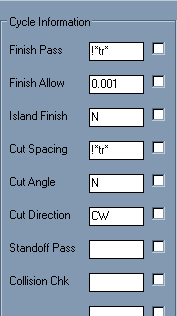
Finish Pass
This parameter allows for the distance from the finished edge of the pocket to the center of the final pass on the pocket. Typically this will be at least one tool radius, but more distance can be allowed to leave material for a finish cutter to make a clean up cut on the shape. Inserting a value of less than a tool radius will result in a pocket that is overcut (too big) and should not be done.
The default value is !*tr* which will always use the tool radius for whichever tool is selected. Any value place in here will be used if possible.
Finish Allow
Finish Allow is an additional offset amount for the shape. Typically the Finish Pass (above) is set to the radius of the tool and this number, Finish Allow, is set to the amount of material you want left for a finish tool. The two numbers are simply added together to produce a total offset from the shape selected for cutting.
For instance if the Finish Pass is set to 0.25" and the Finish Allow is set to 0.001", then the total offset from the shape to the center of the closest tool path will be 0.251".
The default value is 0.001 and any number can be input.
Island Finish
This allows you to specify separate cuts around islands in the pocket, the ISLAND FINISH. Valid responses here are Y or N. If N is specified, then Router-CIM will use the value stored in FINISH PASS. If Y is specified, then Router-CIM will highlight each island, and prompt you for a separate finish allowance for that island. This is in addition to the amount of the FINISH PASS. This is really only useful for Linear Pocketing as Spiral Pocketing will automatically make a finish pass around most shapes by default.
Cut Spacing
This value is set to !*tr* by default, which will use the radius of the tool as the amount to step over between each pass. Depending on the size of the tool, thickness of the material and depth of cut you may want to specify another offset spacing. Realizing that any number smaller than the diameter will be an overlap of the tool paths.
Cut Angle
This is a LINEAR POCKETING value only. Valid responses for this prompt are Y, N or a number. The default is N. If you specify Y, then Router-CIM will prompt you for an angle for the linear motion during the cut. If you enter a number, that will be the angle the pocket is cut at.
Cut Direction
This value applies only to SPIRAL POCKETING, for control of climb or conventional cutting. The two options for this parameter are CW or CCW. This is the control for climb cutting or convention cutting for the bulk of the cut with Spiral Pocketing.
Standoff Pass
This option will allow you to specify either N (no) or a number for the offset amount of the tool around the edge of the shape. If set to a number, the tool path will make a pass around the edge of the shape selected for pocketing offset by the input amount. If it is left blank or N is applied, then no such cutting pass will be made.
Collision Chk
If you are pocketing out an area containing an island or islands, you may enter a Y in the collision check field and Router-CIM will search for tight areas in which your chosen tool might not fit based on the tool diameter and the spacing between the island and the edge of the pocket. In this case it will try and keep the tool from interfering with both the pocket and the island and still pocket as much of the shape as possible.