Veneer Matching in Solid-CIM 3D
Solid-CIM 3D can identify parts that you may want to use the Veneer Matching feature of the Advanced Nesting Module in Router-CIM Automation Suite. A veneer matched set/group is the combination of multiple parts that you want to be nested together in a set configuration so that they are machined from one section of a sheet.
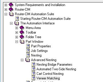
For more information on setting up Router-CIM Automation Suite with the Advanced Nesting Module and Veneer Matching, please refer to the Router-CIM Help Manual under the 'Advanced Nesting' section.
In order for Solid-CIM 3D to identify the parts that you want to be nested as a set/group, a Veneer Match Name needs to be assigned to the 3D solid itself. This can be done in AutoCAD or Autodesk Inventor. The name that you decide for the set/group will be the same for all the parts you want nesting to keep together in your configuration.
Note: The 3D models MUST be drawn in the configuration that you want them in. The 3D models must be situated in the exact way so that Solid-CIM 3D can pick up the correct location points to identify to the Advanced Nesting module the parts relationship to each other.
Note: Use of the X-Axis symbol is required in order to ensure the parts are oriented properly regardless of if the material has a grain definition.
The name needs to be defined in one of the eight label field options that you available to you through Solid-CIM 3D. For more information about adding label fields to your AutoCAD, Autodesk Inventor, Solidworks, Solidedge or Autodesk Fusion 360 parts, click here.
This is an example of how to set up a set/group in Autodesk Inventor:
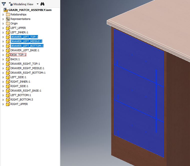
Here, there are 3 Autodesk Inventor parts highlighted that we want to be nested together.
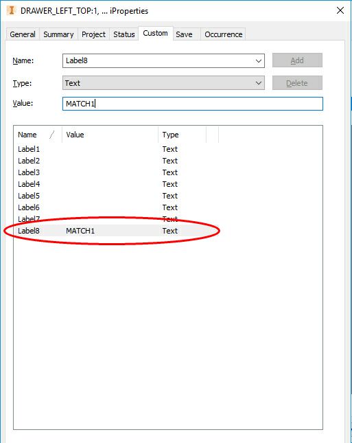
The first thing to do is go into each parts iProperties and create the custom iProperty of Label8. Once Label8 has been created, each of the three parts will need to have a value set in that field that is identical between the parts. In the example below, you can see we named the set/group MATCH1.
For more information about adding label fields to your AutoCAD and Inventor parts, click here.
When this assembly is processed through Solid-CIM 3D, Solid-CIM 3D will collect this information and output it in the Export CSV file so that it can then be brought into Router-CIM Automation Suite.
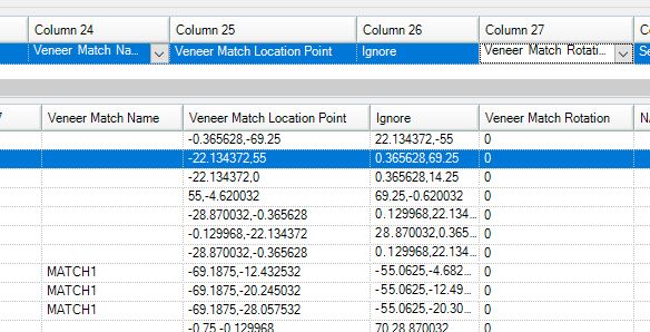
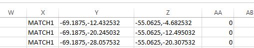
The result in the Export CSV will be configured as below.
Column X is where the Label8 iProperty will be populated, Column Y location point needed for the Veneer Matching feature in Router-CIM Automation Suite Advanced Nesting Module, Column Z is an additional point defining the upper right corner of the part and Column AA is the Veneer Match Rotation Field.
Now that Solid-CIM 3D has collected the correct information, you can then use the Export CSV to create a job in Router-CIM Automation Suite.
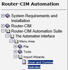
When bringing in the Export CSV, you will need to make sure that Column X, Y and AA are associated to the correct fields in Router-CIM Automation Suite. For more information on how to import the Solid-CIM 3D Export CSV, please refer to the Router-CIM Help Manual in this section: