
When Solid-CIM 3D is installed a new toolbar will be available for shortcuts to all the common Solid-CIM 3D Commands. Each of the icons in the toolbar are explained in the following text.
This command will prompt you to select the solid for Solid-CIM 3D to recognize. All other Solid-CIM 3D commands start from the solid selected with this command.
This should be the first icon you use to recognize the solid model or assembly.
Solid-CIM 3D Toolbar Icon: ![]()
Solid-CIM 3D Ribbon Icon: ![]()
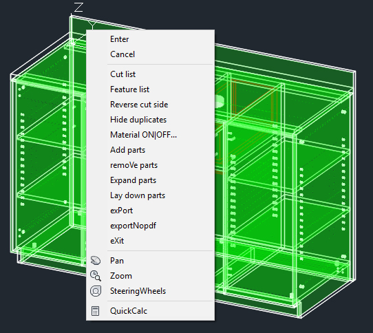
The Expand Solid command will prompt you for a distance or you can drag with the mouse from left to right to expand solids in an assembly apart for closer inspection. This command can only run after the solid has been selected previously with Select Solid.
Solid-CIM 3D Toolbar Icon: ![]()
Solid-CIM 3D Ribbon Icon: ![]()
This command will place all previously selected and recognized solids flat on the world UCS with the shaded side facing up. This allows you to examine the parts more closely to be sure all features are set the way you want them. This command can only run after the solid has been selected previously with Select Solid.
Solid-CIM 3D Toolbar Icon: ![]()
Solid-CIM 3D Ribbon Icon: ![]()
Using this command generates a cut list both on the screen and as a PDF file in the export folder when the part is exported. The on-screen cut list will allow you to manipulate part names as well as part materials prior to exporting them. This command can only run after the solid has been selected previously with Select Solid.
Solid-CIM 3D Toolbar Icon: ![]()
Solid-CIM 3D Ribbon Icon: ![]()
When parts have been selected with Solid-CIM 3D, they will show a cut side shaded (in green by default). If the side that Solid-CIM 3D has selected does not face the direction you wish to have facing up when the part is exported, then this command will allow it to be reversed and have the opposite side face up. This command can only run after the solid has been selected previously with Select Solid.
Solid-CIM 3D Toolbar Icon: ![]()
Solid-CIM 3D Ribbon Icon: ![]()
Allows you to show the duplicate parts that were previously hidden.
Solid-CIM 3D Toolbar Icon: ![]()
Solid-CIM 3D Ribbon Icon: ![]()
Allows you to remove the duplicate parts from the screen display. The duplicate parts will still be included with the quantities upon export.
Solid-CIM 3D Toolbar Icon: ![]()
Solid-CIM 3D Ribbon Icon: ![]()
Allows you to add more parts to Solid-CIM 3D after an assembly has already been recognized. You will be prompted to select all the solids and then Solid-CIM 3D will add the new parts to the output that is exported or reported in the cut list. This command can only run after the solid has been selected previously with Select Solid.
Solid-CIM 3D Toolbar Icon: ![]()
Solid-CIM 3D Ribbon Icon: ![]()
Allows you to remove parts from an assembly that Solid-CIM 3D has recognized so that they are not exported or reported in the cut list. This command can only run after the solid has been selected previously with Select Solid.
Solid-CIM 3D Toolbar Icon: ![]()
Solid-CIM 3D Ribbon Icon: ![]()
Using the Export Assembly button will create a folder with the current drawings name in the export folder location and place a separate part .dwg file for each part in the assembly in that folder along with a CSV (Comma Separated Values) file that can be imported into Router-CIM Automation and processed further. This command can only run after the solid has been selected previously with Select Solid.
Solid-CIM 3D Toolbar Icon: ![]()
Solid-CIM 3D Ribbon Icon: ![]()
Solid-CIM 3D Toolbar Icon: ![]()
Solid-CIM 3D Ribbon Icon: ![]()
Turns off the solid model so that the features behind the model can be seen and worked with. This command can only run after the solid has been selected previously with Select Solid.
Solid-CIM 3D Toolbar Icon: ![]()
Solid-CIM 3D Ribbon Icon: ![]()
Turns on the solid model so that it can be shaded or have materials applied. This is the opposite command to Feature View. This command can only run after the solid has been selected previously with Select Solid.
Solid-CIM 3D Toolbar Icon: ![]()
Solid-CIM 3D Ribbon Icon: ![]()
Allows you to identify the features that Solid-CIM 3D has already recognized. You will be prompted to select a part, and the dimensions of the part will be shown as well as the features that were found. This command can only run after the solid has been selected previously with 'Select 3D Solid'.
Solid-CIM SW (Only available through Solid-CIM 3D for SOLIDWORKS)
Solid-CIM 3D Toolbar Icon: ![]()
Solid-CIM 3D Ribbon Icon: 
Allows Solid-CIM 3D to be run on the exported Step File generated from Solid-CIM 3D for SOLIDWORKS. You will be prompted to locate the step file, and the iscc file if not in the same location as the step file. Solid-CIM 3D will process the step file as if Solid-CIM Connect was run out of SOLIDWORKS.