'SCIM' is the main command provided by Solid-CIM 3D and this command provides access to the numerous capabilities available from Solid-CIM 3D.
A Solid-CIM 3D part in AutoCAD is a named group of AutoCAD objects. A part will consist of one Solid, two Hatches and numerous Polylines. The Solid is the geometric representation of the part. The two Hatches are Top Side Indicators. The current hatch that is displayed is the current Top Side of the part. All recognized Features are represented as polylines. This group of objects represents a Solid-CIM 3D Part. You should never break this group apart or Solid-CIM 3D will fail to understand the part definition.
Typing 'SCIM' at the command prompt in AutoCAD and selecting your solid model should yield results that can be further expanded as described in the rest of this guide.
You can also use the AutoCAD Toolbar or Ribbon by selecting this icon:
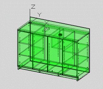
A simple cabinet assembly that has been processed by Solid-CIM 3D would appear as shown. This visual style is AutoCAD’s 2D Wire Frame. The Conceptual visual style will also be used to represent the assembly when selecting parts.
The green tint is the Cut Side hatch object. Each part will show one hatch object. The hatch appears on the side of the solid that has been determined as the Cut Side (Top) of the part.
Cut Side is determined by the following criteria:
•Most material removed on the side
•Identification of the Solid-CIM 3D Top Side symbol
If the side is vertical and has no predominate cutting on one side then the Cut Side determination is random.
