System Settings
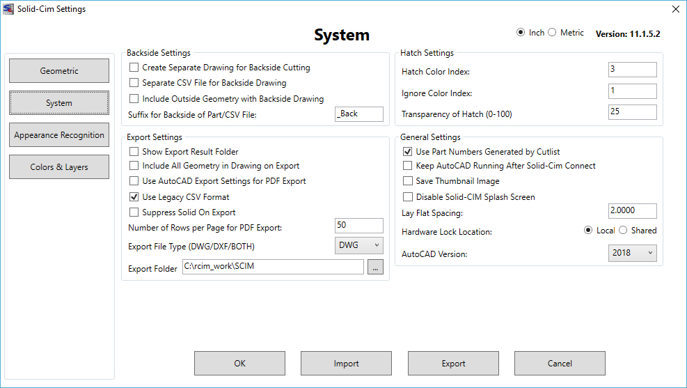
The settings below are unit-less except for the Lay Flat Spacing which is in Inches.
Backside Settings:
The settings in this section are used when a Backside feature is found when running Solid-CIM
Create Separate Drawing for BackSide Cutting (Y/N) <No>: If Yes, a separate drawing is made for all back side cutting. The drawing name has a _Back added to the end of the drawing name. If No (the default), all back side cuts layers are renamed with a _Back added to the end of the layer name. Both methods always position all cuts at locations relative to Z zero with WCS reference.
Create Separate CSV File for BackSide Drawing (Y/N) <No>: If Yes, a separate CSV file is made for all back side drawings. The CSV file name has a _Back added to the end of the name if option Yes if chosen
Include Outside Geometry with BackSide Drawing (Y/N) <No>: If Yes, a the Outside geometry will be included in the BackSide Drawing file on a layer starting with "BACK_" followed by the thickness of the part.
Suffix for BackSide of Part/CSV File <_BACK>: If a Back Side feature is found, and a separate CSV or drawing is created than the suffix added to that file name will match what is typed in this field
Export Settings:
The settings in this section are used when exporting the results from Solid-CIM
Show Results Folder (Y/N) <No>: This option will show the Explorer window of the result folder produced by Solid-CIM 3D Connect. This can be used to validate the result files. Also, it can be used to launch Router-CIM Automation by right-click on the .csv file and open the file using Router-CIM Automation.
Include all geometry in drawing on Export (Y/N) <No>: If True, all geometry (even parts not recognized by Solid-CIM 3D) will be exported into the output folder.
Use Export Settings for Export PDF (Y/N) <No> – Export PDF can be controlled by the Export Settings available in AutoCAD. The AutoCAD command that controls these settings is EXPORTSETTINGS. There are a variety of selections you can define. If this setting is Yes, the Export PDF will use the values you have defined in the EXPORTSETTINGS command. A common selection is to determine if the layout is either Portrait or Landscape when developing the PDF file.
WARNING – IMPORTANT! – Leave this setting as 'No' unless you are sure that your Export Settings for Page Setup Override are correct and valid.
Export PDF is a script that uses AutoCAD commands. All responses to these commands must be accurate and correct. Any mistakes will stop the script and the PDF file will not be produced. You will see that the Export PDF process has been interrupted. To ensure that your Page Setup Overrides are correct run the EXPORTSETTINGS command and select the Page setup option.
If you see a warning like this: 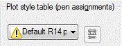 you should set this Plot style table to None selection. Or you should set this Solid-CIM 3D option to No to protect the Export PDF from errors.
Number of Rows per Page for Export PDF <50> – During Export PDF the Cut List is exported to PDF file(s). The number of rows per page determines the limit of rows to be printed per PDF file. The default is 50 rows per page. Each page repeats the header columns to aid in understanding of the information.
Export File Type <DWG> – When exporting the results of Solid-CIM individual part files will be created. This option allows you to choose if the files created are DWG, DXF, or Both DWG and DXF.
Export Folder <C:\rcim_work\SCIM> – When exporting the results of Solid-CIM, use the button to define the parent folder that you would like Solid-CIM 3D to export the results to.
Hatch Settings:
The settings in this section are used to manipulate the hatch pattern in Solid-CIM
Hatch Color Index <3>: The color index for the hatch in the part group. 3 = Green. Color indexes can be found in the AutoCAD documentation.
Ignore Color Index <1>: The color index of the part ignored layer. 1 = Red.
Transparency of Hatch (0-100) <25>: Transparency value for the hatch object in the part group. The number represented is a percent
General Settings:
The settings in this section are used to define layering when the units are metric or standard
Use Part Numbers generated by CutList (Y/N) <Yes>: The Solid-CIM 3D (SCIM) has the optional feature to label each part with a part number. Part numbers are normally used to develop a Bill of Materials (BOM). The presentation of a Bill of Materials consists of labeled parts in a graphic representation and a table of part information and the quantities of each needed to manufacture an end product. The Part Number option is set to No when Solid-CIM 3D is installed and must be set to Yes to activate this feature. This is accomplished using the command SCIMSET. Change the default from No to Yes, press the Verify button and then the Ok button. Part Numbers will be active during any session using Solid-CIM 3D.
| Part numbers are generated when the Cut List is developed. A Cut List can be developed by selecting the CutList option in SCIM or by the Export option in SCIM. Any time the Cut List is developed, part numbers are placed in each part definition. Using the CutList option will display the Cut List and running the command SCIM again will return the display to the graphics of the assembly with part numbers. Part numbers are located on the top and bottom sides of a part. A part number is a member of the Solid-CIM 3D part group definition. The location is normally in the center of the part. If there are Cut Outs in the part, a location is determined elsewhere on the part nearest the center. A part number is an AutoCAD attributed Insert. The attribute is annotative and supports Viewports annotation. Default annotation values assigned to a part number are 1:1, 1:2, 1:4, 1:5, 1:8, 1:10. Annotative objects can be assigned additional values through the use of AutoCAD’s Annotate commands. Part numbers are placed on the _ScimPartNumbers layer. Control of the display of part numbers is handled by turning on or off this layer. Since a part number appears on both sides of a Solid-CIM 3D part, Visual Styles that are transparent will show both representations of the part number. |
Keep AutoCAD Running After Solid-CIM Connect (Y/N) <No>: This option allows for AutoCAD to stay running after the Solid-CIM 3D Connect process. The state of Solid-CIM 3D at this time is a view of all the Cut List tables that can be exported as PDF files. Solid-CIM 3D Connect does not export PDF files during the automatic process. However, there is the command SCIMPDF that can be used to add the Cut List tables as PDF files to the exported data produced by Solid-CIM 3D Connect. By persisting AutoCAD and using the SCIMPDF command in AutoCAD while the Cut List tables are in view, the PDF files will be created. Also, Solid-CIM 3D is available for any validation activities that may be necessary.
Save Thumbnail Image (Y/N) <No>: This allows a thumbnail image to be saved with the created part file so that a preview can be seen prior to opening.
Disable Solid-CIM Splash Screen? (Y/N) <No> - When AutoCAD is opening a Solid-CIM Splash Screen is displayed in order to show that certain functions loaded correctly for Solid-CIM.
LayOut Spacing <2.00>: The spacing between parts for the Lay Down option.
Hardware Lock Location? (Local or Shared) <Local> - By setting this to Local means that the Router-CIM/Solid-CIM hardware lock is plugged directly into the computer using the software. If the hardware lock is located on a network then this should be set to Shared in order for the software to locate the lock.
AutoCAD Version - Shows the installed versions of AutoCAD that are compatible with the installed Solid-CIM 3D version.

