AREC Symbols
The symbols provided allow the AREC feature of SCIM to determine if changes are needed to certain faces of a model prior to exporting the completed geometry. To use the symbols, please refer to the AREC Symbol Specifications section.
You are provided with a DWG drawing that includes the relevant symbols that SCIM is programmed for.
Symbol drawings are located in their default location of C:\Router-CIM\Solid-CIM3D\Symbols for insertion into your drawings/models.
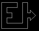
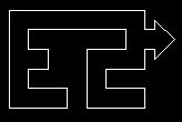
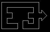
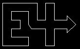
EdgeBand Symbols: Any symbol named 'EdgeBand' will make an adjustment on a single edge of the geometry. The symbol would need to be placed on the face that will have the change affected.
RoundBand Symbols: Any symbol named 'RoundBand' will make an adjustment to all the edges of a particular model. The symbol will only need to be place on a single face and SCIM will make the adjustment to all the edges.
Top Symbol: This symbol will enable SCIM to define the top side of the part per your requirements. By default, SCIM defines the top side of the part by determining the side that has the most material removed. If you need to force a part that has more material removed on the one side but need to have the opposite side as the top, you would need to place the symbol on the appropriate side.
X-Axis (Grain Direction) Symbol: This symbol will enable SCIM to define the X-Axis (grain direction) of a part per your requirements. By default, SCIM defines the X-axis by determining the longest side of the part. If you need to force a part that has a shorter side that needs to be aligned to the X-axis, you need to insert this symbol with the longest edge of the symbol aligned to how you want the part to be aligned along the X-axis.
Start Point Symbol: This symbol will enable SCIM to define the start point of the OUTSIDE defined shape. The start point will be located perpendicular to the center of the symbol. The start point symbol should be located closest to the edge that you want the start point to be defined on.
Bottom Symbol: This symbol will enable SCIM to define the bottom side of the part per your requirements. By default, SCIM defines the bottom side of the part by determining the side that has the least material removed. If you need to force a part that has less material removed on the one side but need to have the opposite side as the bottom, you would need to place the symbol on the appropriate side.
Note: When using the X-Axis (Grain Direction) symbol, the side that you place the symbol on will also become the top side of the part when evaluated by Solid-CIM 3D.
Note: The Top Symbol, Bottom Symbol and X-Axis (Grain Direction) Symbol need to be placed on the largest face that you want to consider the top of the part. When the top of the part has been split into different faces (sections), Solid-CIM 3D uses the largest face (section) and those symbols guide it when they are available.
Symbols include:
EdgeBand1:
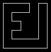
|
EdgeBand2:
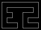
|
EdgeBand3:
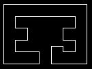
|
EdgeBand4:
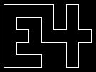
|
RoundBand1:
|
RoundBand2:
|
RoundBand3:
|
RoundBand4:
|
Top:
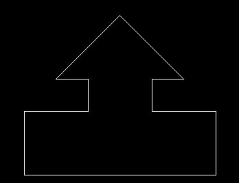
|
X-Axis:
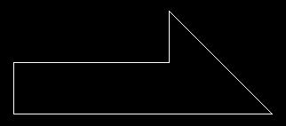
|
Bottom:
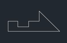
|
Start Point:

|
Note: When the symbols are used, they must be placed within the internal loop of the face in their entirety. The symbols can be scaled (not offset) in a proportional manner. The symbol, when subtracted from the model, cannot yield an intersection with any edge or feature of the model.

