|
|

|

|
|||
|
|
|
|

Tabbing will lift the cutter slightly at certain places-selected by you or selected automatically-to leave parts connected to the sheet. Tabbing will allow you to set the Tabs for your part based on the parameters you set in the Control Panel.
New enhanced Tabbing will now allow Tabbing across even the most complex geometry-even when a single Tab may cross multiple elements.
When setting the Length and Height, please refer to this information:
Length: This sets the Length of the Tab, in units. If you leave this field blank, but select either Yes or Automatic to Tabbing, then you will be prompted during the Cut for the correct Tab Length. When setting the Tab Length, determine the desired tab length you need and then ADD the diameter of the tool that you are using in order to get the correct amount of material left of the tab.
NOTE: You can set the length of your tab to a negative number between 0 and 1. Router-CIM will interpret this as a percentage. For example, if you set the Length of the tab to -0.4, you will receive a tab that will be 40% of the total perimeter of the geometry you are tabbing.
Height: This sets the Height of the Tab, in units. If you leave this field blank, but select either Yes, or Automatic to Tabbing, then you will be prompted during the Cut for the correct Tab Height. Determine the height of the tab you need and then you will need to do the calculation since some of the height will be taken off by the tool moving up and over the tab if using 3D tabs.
See example based on using a 1/2 inch tool:


Minimum Radius: This sets the minimum radius that a tab can be placed on. Option is available with Auto and Tab by Distance.
NOTE: When using the Minimum Radius feature with the 'AUTO' tabbing, the cut cycle needs to have the 'Round Corners' option set to N if applicable. The Minimum Radius feature does not support using the Round Corners option.
Router-CIM will make 3-D tabs that ramp up and ramp down by default. This is useful for modern machines that use high speed, high precision machining.
Tabbing is either 2D or 3D based on the 'Use 3D Tabs' option:
To learn more about 2D and 3D tabs, please refer to the '2D or 3D Tabs' section.


See the Tabbing options below:
If you select NO, then no Tabbing operations will occur.
'YES' to Tabbing
This will set up Tabbing to run and will prompt you for the locations for the Tabs before the Cut is finished. You may pick as many locations as you need for the Tabs.
Note: Be sure to pick on the tool cut path for the Tab location. If you select the geometry for a Tab location, you will not get a Tab placed in that spot.

When Automatic is set, you will be prompted for the number of Tabs you wish to have on the part in addition to the Height and Length, and Router-CIM will divide the number of Tabs across the part evenly spaced.

When 'TAB at Start' is set, this will produce a Tab immediately after the lead-in. The overlap will automatically cut the Tab off at the end of the cut. This will hold the part at the cut start for the duration of the cut. You will still need to set your Height and Length.

When 'TAB by Distance' is set, you will receive Tabs at the distance interval that you have set. Smaller parts get less tabs while larger parts will receive more tabs. You will still need to set your Height, Length and Distance.

After your parts are initially cut:
Bring up Control Panel/All Stats page
•Set Tabbing from Yes, Auto or Tab by Distance to No.
•Choose Center Line Cut as the Cutting Cycle.
![]()
•Click 'OK' at the bottom left of the Control Panel/All Stats page.
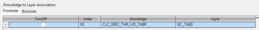
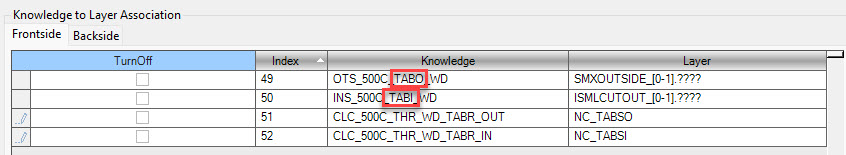
• Type TABR at the command line, hit Enter. When working within Router-CIM interactive, cut paths will be executed on geometry that is on the TABR layer. It will use the current settings in the Control Panel to accomplish the cuts.

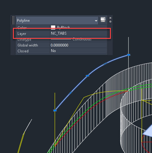
NOTE: The geometry located on layer NC_TABS will be an open shaped offset from the edge of the geometry by the radius of the tool in the knowledge that created the tab. The knowledge created for the tab removal should use a tool with the same diameter as the tool used to create the initial tabbing cut.