|
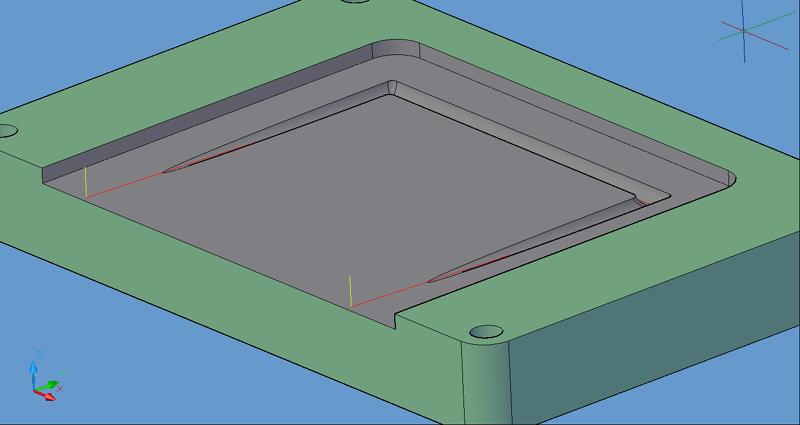
3D Poly Center will follow a 3D Polyline drawn and geoshaped. The tool path will start at the Safety Plane, plunge to the start of the cut and then follow the 3D Polyline to the end and finish by retracting straight up to the Safety Plane.
This is a center cutting cycle and no tool radius compensation should be used.
This cycle is used to turn any 3D polyline into a tool path. Draw the 3D polyline on layer NC_SHAPE (or Geoshape a 3D polyline), ensure Cutter Comp is set to No, and click Cut. This cycle will add vertical lead-in and lead-out at the start and end points on the polyline. This cycle is used for cutting sloped slots or varying depth engraving cuts.
|

3D Poly Center tool path
The following parameters effect the toolpath creation:
Cut Direction
The direction of the cut can only be clockwise (CW) or counter-clockwise (CCW). This even applies to open shapes where this direction really has no meaningful relationship to the geometry selected. Any closed shapes should have the direction set accordingly and any open shapes should be set to CCW as all shapes in AutoCAD and Router-CIM are CCW by default.
See the Cut Direction section for more information.
Lead Feed
This sets lead-in and lead-out feed rates. The default is 0.5, Router-CIM's standard 50% feedrate for lead-in and lead-out. Whatever number you set this variable to is a percentage of max feedrate set in the Control Panel. Setting the number to a value greater than 1.0 will give you an exact feedrate.
See the Lead Feed section for more information.
XY Stock Allowance
Placing a value in this parameter will offset the tool path to leave material for a finish pass. For instance, placing .125 in the XY Stock Allowance and cutting a 6.4 x 4.0 shape will actually leave a part that is 6.25 x 4.25, by adding .125 to the offset of the tool path all the way around the part.
See XY Stock Allowance for more information.
Z Stock Allowance
Placing a value in Z Stock Allowance will change the Total Cut Depth by the number entered. You can use this if you want to leave a small amount of material on the bottom of a part, or if you intentionally want to overcut a part to be sure it is cut all the way through.
Entering a positive number will move the tool path UP in Z, leaving more material for a finish pass.
Entering a negative number will move the tool path DOWN in Z, past the normal Total Cut Depth.
See Z Stock Allowance for more information.
**Changing values in the cycle parameters may yield unexpected results with some settings or on some geometry. Examine the toolpath and NC Code carefully before running your machine tool if you change these default settings.