Creating a 'SLOT' in AutoCAD using Router-CIM
You can use Router-CIM within AutoCAD to draw the geometry of a SLOT in either the horizontal (aligned with the X axis in AutoCAD) or vertical (aligned with the Y axis in AutoCAD) direction. A Slot is defined as a rectangular piece of geometry with arcs on the end that match the width of the rectangle.
To use Router-CIM within AutoCAD to create what is defined as a SLOT, you will need to open AutoCAD and start Router-CIM within AutoCAD by selecting the Router-CIM icon under the toolbar or ribbon:

This will start Router-CIM within the AutoCAD drawing. If you are using Router-CIM Interactive, make sure to select the correct post processor from the Configuration Wizard. Select here for more information on the 'Configuration Wizard'.
Once Router-CIM has been successfully started within the AutoCAD drawing, you can then type in the command line SLOT.
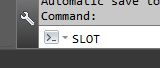
This will start the SLOT command.
NOTE: If you type in SLOT and it comes up with Unknown Command, it means that Router-CIM was not started in that AutoCAD drawing.
The following information was based on a slot that was drawn centered on a 24 x 12 rectangle that was drawn from 0,0 in AutoCAD in Quadrant 1.
When the command is active, you will be prompted to follow a series of questions.
The first question is asking for the center point of the slot:

The value that should be entered is either based on a button click or defining the X and Y coordinate.
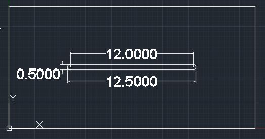
The next question will ask for the distance between the two centers of the arcs. You can also think of this as the length of the rectangular feature:

The next question will ask for the DIAMETER of the arcs that are at the ends of the rectangle. You can think of this as the width of the rectangle.

The final question will be whether to draw the SLOT aligned with the X axis in AutoCAD, Horizontal (H) or should it be aligned with the Y axis, Vertical (V).

Once this final question is completed, Router-CIM will draw a SLOT according to the information given.
NOTE: A SLOT will be drawn as 2 lines and 2 arcs that are NOT joined.
Here is an example of a SLOT drawn according to the information defined above: