|
This version of Spiral Pocketing (in both the In-Out and Out-In cycles) uses a different algorithm and contains many options to control the creation of the tool path than the other Spiral Pocketing cycles. This method allows for more complex geometry to be handed to the tool path generator.
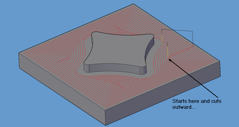
Spiral Pocket In-Out will start at a point inside the pocket and create offset tool paths, moving toward the outside of the pocket. There are parameters to allow a plunge start or a ramp start, and also options for keeping the tool down while in the pocket or allowing the tool to pick up and move to another are of the pocket to continue the shape.
Download sample drawing here. |

Spiral Pocket In2Out tool path.

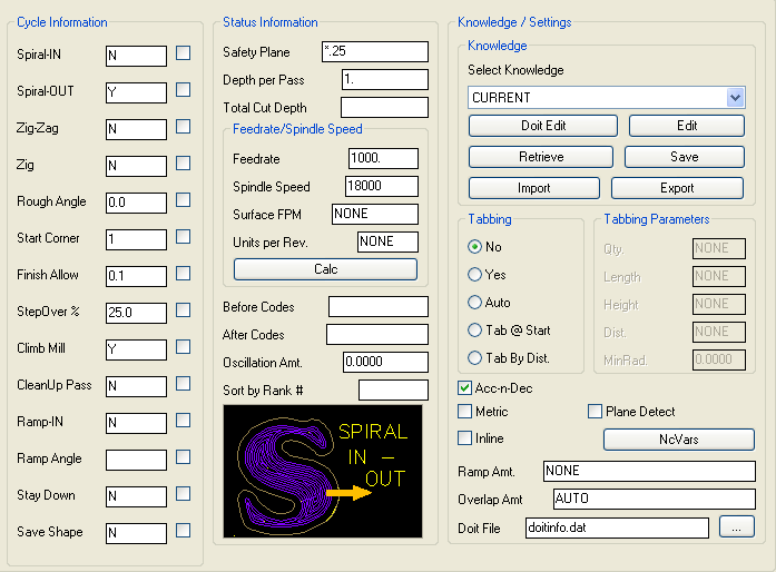
Spiral In2Out parameters.
The following parameters effect the toolpath creation:
Spiral-IN
Spiral – OUT
Zig-Zag
Zig
Rough Angle
Start Corner
Finish Allow
Step Over %
Climb Mill
CleanUp Pass
Ramp-IN
Ramp Angle
Stay Down
Save Shape
Safety Plane
The safety plane is the index plane Z location. If a ' * ' is used as the first character, that position is absolute in world Z coordinates, otherwise it is considered to be the distance above the shape.
Depth Per Pass
This controls the depth per pass in Z. It is also the initial Peck Increment.
Total Cut Depth
This parameter controls the total depth of the cut. If a ' * ' is used as the first character, that position is absolute in world Z coordinates. If it does not, then that distance is considered to be the distance below the initial shape.
Feedrate
Initial feedrate to start the drilling operation.
Spindle Speed
The RPM value to use for the spindle for this tool path.
Before Codes
Values placed here will be output in the cut cycle before the tool enters the material, typically at the height of the Safety Plane once the tool length compensation is set.
After Codes
Values placed here will be output in the cut cycle after the tool has retracted from the cut, typically at the height of the Safety Plane after the cut is finished.
Sort by Rank #
A numeric value to use for the tool path created to allow the Sequence to place cuts in a specific order when the code is created.
**Changing values in the cycle parameters may yield unexpected results with some settings or on some geometry. Examine the toolpath and NC Code carefully before running your machine tool if you change these default settings.
