2 sided nesting in Router-CIM
Requires the Router-CIM Advanced nesting module
Description:
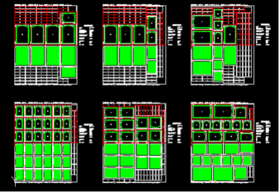
2 sided nesting allows for machining on the back side of a nested sheet, then the sheet is flipped along the X axis and the front side is cut. Note that the back side is cut first. Outside parts can be cut half way through on the back then all the way through on the front, or they can be just cut all the way through on the front.
Requirements:
Job:
The 2 sided nesting is activated by checking the box in the Advanced Nesting tab that says “Enable Backside Nesting”
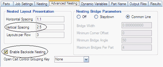
Also in the Advanced Nesting tab, the vertical spacing needs to be set at 2.5 or more. This ensures that there is enough room to mirror the sheets.
Note that 2 sided nesting requires rectangular stock only, irregular stock shapes with more than 4 sides will not be mirrored.
Parts:
The parts will have both front and back side geometry drawn in one part drawing, dxf, or macro.
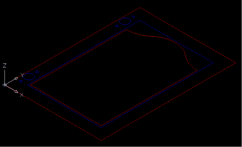
In the part example above, the red geometry is cut on the front side of the sheet, and the blue geometry is cut on the back side of the sheet. Both the front and back geometry are in the same drawing, dxf, or macro file.
The front and or back geometry can have negative thickness. If you want your knowledge to cut to the geometry thickness, then your total cut depth can either be left blank, or have a capital A, or a backslash and a value. Blank or A will make the cut depth to the geometry thickness. A backslash and a value will cut that value more or less than the geometry thickness:
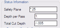
This example will cut .005 MORE than the geometry thickness.
If the geometry is -.75 thick, the cut depth will be -.755
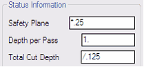
This example will cut .125 LESS than the geometry thickness.
If the geometry is -.75 thick, the cut depth will be -.625
Doit files:
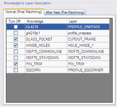
When you edit the doit file, there are now two tabs:
Normal (Final Machining) tab and an After Nest (Pre-Machining) tab.
The Normal (Final Machining) tab is the associations for the front side of the material. The front is actually cut after the back side is cut.
If you want to cut half way through on the front, and half way through on the back, then you need a knowledge and layer association that cuts half way through for both the Normal tab and another (or the same) knowledge association for the After Nest tab.
If you want to cut all the way through on the front side, then that knowledge / layer association should be done in the Normal machining tab. You would never cut all the way through on the After Nest because that would separate all the parts and you could not flip the sheet over!
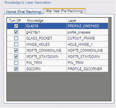
The After Nest (Pre-Machining) tab is the associations for the backside cutting operations. The backside operations are cut first so new sheets are loaded backside down first.
Trim cut:
A trim cut is made along the edge of the back side sheet. This trim cut ensures a good edge to place up on the pop up pins when the sheet gets flipped over.
Router-CIM automatically makes geometry on layer pin_trim. You need a knowledge named pin_trim associated to layer pin_trim in the after nest doit file. This knowledge is a centerline cut set to offset by the tool radius, cut to the RH and CCW direction.
The pin_trim geometry is offset by ½ of the edge allowance and will be shaved off the back side of the sheet and the origin of the main nccode file will be shifted by that amount.
Results:
When the job is run, the results will have two NC Code files for each sheet.
The regular sheet name and one with PRE in the name. The PRE is the back side and it is run first.
The schedule file will have the PRE file first, then the regular NC Code name. This makes the back side of the sheet, flip it over, then the top side of the sheet.
Operation:
| 1) | In the Advanced nesting tab, the Enable Backside Nesting box is checked and the vertical spacing is set to 2.5 or more |
| 2) | Parts are added to a job. These parts must have geometry for both front and back side machining. |
| 3) | The DOIT file has associations for both the front and back sides |
| 4) | The After Nest tab in the DOIT file requires a layer to knowledge association called pin_trim. This is the trim cut to ensure a stable edge to flip the sheet against. |
| 5) | Run the job. |
| 6) | Load the sheets backside up at the CNC. The backside is the first machining to be done, then the sheet is flipped over and the front side machining is done. |
| 7) | The results will have 2 NC Code files for each sheet. The regular sheet name and one with PRE in the name. The PRE is the back side and it is run first. |
| 8) | The schedule file will have the PRE file first, then the regular NC Code name. This makes the back side of the sheet, flip it over, then the top side of the sheet. |
Example Schedule file:
1,MDF75_1PRE.OUT,1,1,00:00:00,00:00:00
1,MDF75_1.OUT,1,1,00:00:00,00:00:00
2,MDF75_2PRE.OUT,1,1,00:00:00,00:00:00
2,MDF75_2.OUT,1,1,00:00:00,00:00:00
3,MDF75_3PRE.OUT,1,1,00:00:00,00:00:00
3,MDF75_3.OUT,1,1,00:00:00,00:00:00