|
|

|

|
|||
|
|
|
|
Definition of terms used:
Face – The surface of a solid. A solid can have many faces to define a complete solid.
Edge – A face is bounded by edges. Each edge of a face represents a segment of the bounded face.
Polyline – The AutoCAD object that consist of a series of lines and arcs.
Segment – A geometric element between two consecutive vertices in a polyline. The geometric element is a line or arc.
Vertex – The end points of a segment. A polyline can contain many vertices.
Marker – This document uses the term “marker” to indicate that a face has been marked with an appearance or a symbol to indicate edge band processing by AREC.
The term “side” is not defined in AREC. A “side” is not a property of any AutoCAD object used to define parts and SCIM features. Solids only have faces and edges. Polyline features only have segments and vertices. There is no definition for “side”.
“Side” is a term used to indicate there are one or many edges/segments defining a portion of a solid that needs a single edge banding definition. “Side” has no reference to a single object used in AREC.
Do not confuse the need to edge band a “side” with edge banding edges in AREC. Only edges and polyline segments are recognized in AREC.
Example of the terms Edge and Side:
The above part, viewed from the top, has four “sides” (front, back, left and right) and six edges (three lines and three arcs). AREC processes the edges and does not have a definition of “side”. “Side” is simply being used to describe a series of edges that represents a possible single edge banding requirement.
Relationship between Edges and Segments
AREC uses the edges of a face to form the polyline used for defining the Outside feature in SCIM. Each edge of a face usually equals one segment in the polyline definition. AREC depends on the one to one relationship between an edge and the developed polyline segment. However, a spline edge is converted to multiple polyline segments and breaks this one to one relationship between the edge and segment.
IMPORTANT: AREC depends on the one to one relationship between an edge and the developed polyline segment.
One-to-One Edge/Segment relationship:
|
|
The solid on the left has six edges. The polyline on the right has six segments. The one to one relationship between each edge of the solid and edge segment of the polyline is maintained. AREC can properly process any edge banding markers applied to the solid. Each square mark is the start/end of a segment of the Outside polyline feature in SCIM.
To edge band the curved “side” of this part place edge band markers on all three faces to be edge banded. The three edges of these faces will align with the resultant curve segments in the Outside polyline. |
|
One-to-Many Edge/Segment relationship:
|
|
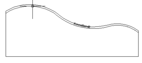
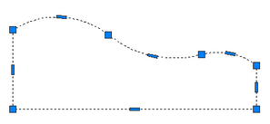
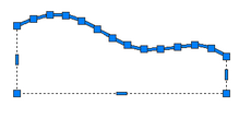
The solid on the left has four edges. The polyline on the right has many segments. This is the result of spline edge definition being translated to polyline segments for the Outside feature. A spline is a single geometric element. A polyline does not have spline segments. The spline is converted into line/arc segments to define the polyline. The one-to-one relationship is broken. Placing a marker on the curved face in the solid will not result in the correct results for edge banding on the polyline. See “Procedures” for possible resolutions.
Procedures
The basic procedure for marking faces for edge banding is described in the operator’s manual for AREC. The procedure defined below allows for a possible resolve of the one-to-many relationship situation with limited usage.
The “ROUND” type appearance in AREC indicates that an edge band is to be applied to all segments in the Outside polyline feature. No one-to-one relationship between the solid edges and the polyline segments. All segments are processed with the same edge banding definition.
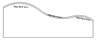
The “ROUND” type appearance and the “EDGE” type appearance can work together to apply edge banding to a series of segments. Place a “ROUND” marker on one of the faces in the series. In the above one-to-many example, place the marker on the spline face. To skip the other three straight edges place a “EDGE” marker on each of them and set the offset value to 0.0.
When AREC sees a “ROUND” marker in combination with “EDGE” markers that have a zero offset value, the “ROUND” offset value will be applied to ALL segments except those previously marked with an “EDGE” marker.
NOTE: A value of 0.0 for the offset of any edge band appearance definition is a valid value. There may be cases where edge banding is required but no addition/removal of material is necessary. Only in the case of using a “ROUND” and “EDGE” markers together does the offset value of 0.0 indicates to ignore the marked segment.
The result in the one-to-many would be: